[BUILD] 1176 Rev F/G - new board, new transformer!

GroupDIY Audio Forum

Help Support GroupDIY Audio Forum:

This site may earn a commission from merchant affiliate links, including eBay, Amazon, and others.

mnats

Well-known member
Joined
Jun 3, 2004
Messages
984
Location
Australia
Having trouble with this build? Read the 1176 FAQ.
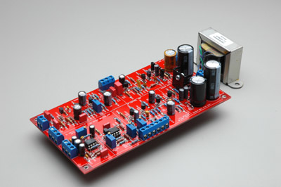

Click for large image

About eight months ago Ed Anderson and I were discussing the Bournes B11148 output transformer originally used for the 1176 Revision F. He mentioned that he had CJ do a hacksaw job on one and had the winding info.

I had planned to do a new board based on this revision as an alternative to the usual G1176 and thought it would be nice to have an authentic reproduction of the original output transformer to go with it. The idea was to make something with the audio path like the original F with a T attenuator, O-12 input transformer reproduction, original transistors (or modern direct replacements) and component values and the B11148 repro on the output. Just another color of the 1176 to add to the existing palette and a new take on an old favorite.

It might surprise some that the Rev F with its class A/B output stage has less harmonic distortion than any of the other revs - nice if you're looking for a fast compressor without a lot of added coloration. Though I haven't figured out exactly why yet, the new Rev F board measures below 0.06% THD while the best figure I can get with the G1176-type board is around 0.143% THD.* The B11148 repro adds a subtle lift at the high and low extremes while the Lundahl or OEP commonly used in the G1176 doesn't.

The resulting PCB design matches the others in the series in form (Rev A and D) and is just like the original circuit except in two ways. The 7824 regulator was swapped for the quieter LM317. Also, the IC input of the Rev G and later was added to the board like the G1176 as an option.

Schematic

Overlay

BOM

Boards available!

* The Rev F and G1176 were both measured with the IC input option instead of an input transformer. The Rev F had the B11148 repro on the output while the G1176 had the Lundahl LL5402.
 
look at what mako's PCB sets cost now, and what mike sells the parts for in the hairball audio store... the price for this rev should be about the same as any other, plus or minus a few bucks.

ed
 
mnats said:
After the auction I will be posting the usual PDF with schematic, parts list and self-etch files. Boards will be offered in the White Market as well. Hairball will offer the new B11148 output transformer which can also be used with the G1176, the LA3A output or the 1109.

Cool beans,

I'd love to add one of those guys to my Rev J board, which currently has a Lundal on the output and a St. Ives 31267 on the input.

How difficult is it to adapt the Rev J to the B11148 output transformer?

Mark
 
Biasrocks said:
How difficult is it to adapt the Rev J to the B11148 output transformer?

Seems straight forward.  Have a look at the J layout on the revision F schematic:
http://www.waltzingbear.com/Schematics/Urei/Urei_1176LN_series_F_page_3.htm

You could also add an attenuator and CM-3837-1 if you like.

Congrats to Mako on another great project offering and Ed for the transformer!  It's now possible to build all the revisions (A-H) with amazing accuracy.

Mike
 
The auction for the new board with semi-kit has opened on Ebay.

http://cgi.ebay.com/ws/eBayISAPI.dll?ViewItem&ssPageName=STRK:MESELX:IT&item=250437404561

All proceeds will be donated to Prodigy-Pro to help maintain this wonderful forum.

Here is a great opportunity to be the first to get your hands on a great new offering and help the forum!

A huge thanks should go to Mako (mnats) and Ed Anderson for their work in making this possible.

Happy bidding!

Mike
 
mnats said:
Though I haven't figured out exactly why yet, the new Rev F board measures below 0.06% THD while the best figure I can get with the G1176-type board is around 0.143% THD.*

This is quite interesting. I guess you got rid of that solid 3rd order distortion of G1176 somehow? With distortion trim it's only possible tune the input stage feedback loop, mostly affects 2nd order and its multiples it seems.

But there's that 3rd order spike, always much higher than the 2rd order spike, I guess in output stage somewhere, and it won't budge with anything.

Maybe your new transistor choices fixed this somehow? I don't see a mere layout out could bring such difference...
 
Echo North said:
The auction for the new board with semi-kit has opened on Ebay.

http://cgi.ebay.com/ws/eBayISAPI.dll?ViewItem&ssPageName=STRK:MESELX:IT&item=250437404561

All proceeds will be donated to Prodigy-Pro to help maintain this wonderful forum.

Mike, you are a legend for doing this. Sometimes I think some of you guys are too good!

Mako, you continually impress me with your work. Well done.
 
Thanks!

These auctions are really started by Ed and Mako, so a huge thanks to them.

Thank you to everyone who helped make the auction a success!

Mike

 
rodabod said:
Mike, you are a legend for doing this. Sometimes I think some of you guys are too good!

Mako, you continually impress me with your work. Well done.
I'll admit that the auctions were originally my idea but Mike has always done the leg work involved in getting them up on Ebay and this last time has donated a substantial portion of the parts. So don't let him fool you!

The other thing I'll say is that Ed has had a pivotal role in each of the newer revisions I've done and they wouldn't have been as good or authentic without the benefit of his knowledge. Big thanks also to CJ who as mentioned took his hacksaw to Ed's B11148 to get the winding info.

In regards to the lower distortion posted by Kingston I think that's right but can't be sure until I put the board back into my test jig box.

Now that we've come full circle with this new take on the circuit behind the G1176 I might be able to get around to the other projects I've had on the back burner...
 
mnats said:
In regards to the lower distortion posted by Kingston I think that's right but can't be sure until I put the board back into my test jig box.

Looking forward to any results regarding this if you ever find the time to compare.
 
Kingston said:
mnats said:
Though I haven't figured out exactly why yet, the new Rev F board measures below 0.06% THD while the best figure I can get with the G1176-type board is around 0.143% THD.*

This is quite interesting. I guess you got rid of that solid 3rd order distortion of G1176 somehow? With distortion trim it's only possible tune the input stage feedback loop, mostly affects 2nd order and its multiples it seems.

But there's that 3rd order spike, always much higher than the 2rd order spike, I guess in output stage somewhere, and it won't budge with anything.

Maybe your new transistor choices fixed this somehow? I don't see a mere layout out could bring such difference...

FWIW, I've made some measurements on a Rev J 1176 that a friend has heavily used for a year.
OEP in&out.

Only some raw facts:

- bass roll-off under 200 Hz
- 3d harmonic greater than 2nd, with fundamental from 20 until about 600 Hz [progressive dim of difference, at 600 Hz 2d and 3d equals]
- with 600 Hz to 20K fundamental, 2nd harmonic become progressively greater than 3rd.
- THD 0.07%

--- demagnetized the OEP input trafo with 0-3V 3V-0 sine sweep at 30 Hz

- no more bass roll-off
- 2d harmonic always steady greater than 3d, with any fundamental frequency
- THD 0.06%


I recently finished a dual unit with the older mnats board, but only today finished tweaking. When I posted that I still had some 0.1-0.2%THD 3rd harmonic and was wondering where things went wrong. Turns out it was the transformer set up, although I don't quite see why.

Now I have Lundahl in (1:1 allows a completely stupid amount of compression) and Lundahl out (1:2 allows a stupid large amount of gain), and finally THD sits at about 0.06-0.07%. It's mostly 3rd harmonic. I managed to tweak 2nd harmonic to negligible level. This was the RMAA test suite so don't know about test tones in detail, I guess 1000hz.

Another observation. This is the first build (tube, chip, solid state) where I have ever actually *heard* different caps affecting audio. I found a dramatic difference in an unexpected place: those two 0,22uF caps! I had one unit with Panasonic SMF and another with Wima MKS2(like in the mnats picture above). Those MKS2 are transient poison! I wondered if the MKS2 unit had slightly broken transistors, but it was just those caps. Any acoustic guitar strumming immediately shows what they do.

I don't get it. These differences don't measure on RMAA (THD, noise) for example, but can be clearly heard if you know what to listen to.  ???

Then I went through some side by side testing with the three 1uF caps. Again, Wima MKS2 was really bad, I urge anyone to try, although the difference was less dramatic as with those 0,22uF ones. Wima MKS4 (250V) on the other hand sounds great, as does Mundorf M Cap. All relatively cheap.

And the sound of this unit... How much better can solid state sound get?  ;D
 
mnats said:
* The Rev F and G1176 were both measured with the IC input option instead of an input transformer. The Rev F had the B11148 repro on the output while the G1176 had the Lundahl LL5402.

mnats, I think it's this one that explains the difference. What was the output Lundahl ratio?

I got THD to 0.06-0.07% on your older layout, lundahl input 1:1 (should not make a difference even if it was 2:1 step down), lundahl output 1:2. Somehow the output stage likes to see a step up.
 
Kingston said:
Another observation. This is the first build (tube, chip, solid state) where I have ever actually *heard* different caps affecting audio. I found a dramatic difference in an unexpected place: those two 0,22uF caps! I had one unit with Panasonic SMF and another with Wima MKS2(like in the mnats picture above). Those MKS2 are transient poison! I wondered if the MKS2 unit had slightly broken transistors, but it was just those caps. Any acoustic guitar strumming immediately shows what they do.
Then I went through some side by side testing with the three 1uF caps. Again, Wima MKS2 was really bad, I urge anyone to try, although the difference was less dramatic as with those 0,22uF ones. Wima MKS4 (250V) on the other hand sounds great, as does Mundorf M Cap. All relatively cheap.

And the sound of this unit... How much better can solid state sound get?  ;D

Should I swap the 0,22uF caps on my the Rev D? they are WIMA MKS2 too... I don't have any others to compare, I need to check between the schematics if they are in the same place ;)

Thanks for the observation...

Eddie  :-\
 
SaMpLeGoD said:
Should I swap the 0,22uF caps on my the Rev D? they are WIMA MKS2 too... I don't have any others to compare, I need to check between the schematics if they are in the same place ;)

Yes they are used the same in rev D. And yes, I would recommend Panasonic SMF there instead. I have not tested anything else but these two, but the difference was notable.
 
Kingston said:
SaMpLeGoD said:
Should I swap the 0,22uF caps on my the Rev D? they are WIMA MKS2 too... I don't have any others to compare, I need to check between the schematics if they are in the same place ;)

Yes they are used the same in rev D. And yes, I would recommend Panasonic SMF there instead. I have not tested anything else but these two, but the difference was notable.

Ok! thanks for the tip!
I think I have some SMF hanging around ;)
Thanks!

Eddie :)
 
Kingston said:
I don't get it. These differences don't measure on RMAA (THD, noise) for example, but can be clearly heard if you know what to listen to.  ???

Then I went through some side by side testing with the three 1uF caps. Again, Wima MKS2 was really bad, I urge anyone to try, although the difference was less dramatic as with those 0,22uF ones. Wima MKS4 (250V) on the other hand sounds great, as does Mundorf M Cap. All relatively cheap.

And the sound of this unit... How much better can solid state sound get?  ;D

Thanks a lot for the documentation!
I'll try it with my 1176.
I am also hugely curious on how is possible to measure the differences of these capacitors..
now exactly working on/studying that., waiting for a cheap indian full-featured LCR meter and a Sencore LC-75, hoping things will be more clear 

 
mnats, a question about your new rev F schematic.

Why have you changed C9 47uF to 1uF? and C10 1.0uF to 0,15uF?

I can see you use these in Rev A and D. Where does the difference come from?
 
Kingston said:
Why have you changed C9 47uF to 1uF? and C10 1.0uF to 0,15uF?

I can see you use these in Rev A and D. Where does the difference come from?
The schematic from the JBL Pro site. The idea of the new F (and earlier A, D) was to stay as true to the audio path of the original units as possible. I'm not certain that the schematic there is the definitive version, however.

As usual, I've included pads to accommodate different pitch coupling caps in case you want to try other values, wound construction film caps, electrolytics etc.
 

Latest posts

Back
Top