[BUILD] 900 Rack Power Supply DIY project and PCB

GroupDIY Audio Forum

Help Support GroupDIY Audio Forum:

This site may earn a commission from merchant affiliate links, including eBay, Amazon, and others.

mnats

Well-known member
Joined
Jun 3, 2004
Messages
984
Location
Australia
I needed to rack a DBX 900 module recently. The modules require +/-15V and +/-24V. I decided to use their FS900 power supply schematic but made a few changes like adding circuit protection for bonehead wiring errors and a 50 cent cap for improved ripple performance. Since I went through the trouble of designing a board, I just decided to have some prototype boards professionally manufactured:
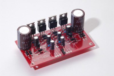


It's double-sided, but you could probably just etch the bottom layer and run a few wires from the bottom of the board. Self-etch files, BOM and schematic here: http://mnats.net/files/FS900+_V1.0_DOC.pdf

The layout has been tested and appears to work fine, but the module itself has some problems that I now need to work out :( Regulators and pass transistors all on one side - use insulators and attach to a single surface for easy mounting.

There are a few prototype boards left that I'll sell from my website.
 
livingnote said:
Ooooh red board is nice too though  :-* Where do you get those made?

Gold Phoenix. Kinda brash and not as cool as your black boards though. Also a boring layout compared to your SSL.

Hey, meant to say thanks for your inspirational PCB design post!

radiance said:
Very handy psu. Thanks...paypalled you for 1 board

OK, nice to know others need the same kind of board.
 
Gold Phoenix. Kinda brash and not as cool as your black boards though. Also a boring layout compared to your SSL.

Hey, meant to say thanks for your inspirational PCB design post!

Wow thanks Mnats. I've always been quite an admirer of your work too.

Funny how a project can just eat you up like that, eh? We seem to have been bitten by
a similar bug... :D


HA gueeeeeeessss? I was JUST in the other thread talking about how cool it would be to
juice up a tranny with +/- 24V on the GSSL. Lemme guess, you have this secret love for
PSU too, right? On the GSSL I was planning on making (here comes) a power supply with
six regulators, two times +/- 15 and one time +/- 24 and standing them all up in a row,
now I was thinking of just giving them all heatsinks individ but now that you mentioned
giving them all one piece of Alu...that would make a totally kickass thing, I did that
on my lab supply but didn't have the brain to go "put one of those on the GSSL".
Not only is the big piece of Alu a heatsink, but if you build it right then
it serves to shield the rest of stuff from power tranny.  *bing*  Thanks :)


By the way - why a discrete supply for 24 and a 317 for 15? Oh and while we're picking
stuff apart - why the double emitter follower?
 
Interesting.  Very nice.  I just threw in a JLM powerstation in my empty 900 rack but this is a nice little beast.

I also took off all those terminal strips at the back, drilled out holes, and put 1/4" jacks on nearly everything (I think it was 2 TRS and 2 TS) in my 900 rack.

Now I just need to put something more in it than 2 DBX 903s!  I'd like to put some of JLM's compressors in there.

CC
 
radiance said:
To get regulated -24 +24V do you use a -24 0 +24 transformer with this ?
Should be OK with minimum 40V center tapped so yeah, two 24VAC windings will be fine. Just make sure the regulators get bolted to something big enough.

radiance said:
Or is there some voltage doubling going on?

Check the schematic - no charge pump in this baby. BTW, your board shipped today.

livingnote said:
By the way - why a discrete supply for 24 and a 317 for 15? Oh and while we're picking
stuff apart - why the double emitter follower?

I'm just a dumb repair guy and the schematic is basically just copied from the FS900.

Not following your next question - there's the Darlington pass transistor (Q1, Q3) and a couple of TO-92 packages (Q2, Q4). The Darlingtons do the heavy work while the smaller ones sit there looking at the current through the resistors near the outputs. When things get too hairy (like a short circuit), they turn on to limit the current thorough the Darlingtons and save you some money.

Someone else could probably give you a better description!
 
>>I'm just a dumb repair guy and the schematic is basically just copied from the FS900.

Do I know that from somewhere?

>> When things get too hairy (like a short circuit), they turn on to limit the current

I was thinking as much - I do remember very fondly seeing a dear friend do a
"really fast discrete PSU" and killing the damn thing every time he stuck his probe
in wrong - slapstick.
 
livingnote said:
Do I know that from somewhere?

Yeah - it was discussed here: http://www.groupdiy.com/index.php?topic=8024.msg95192#msg95192 but the original schematic is here: http://www.dbxpro.com/vintage_download.php?product=FS900

radiance said:
Just received my psu board. Again, very well made.

Great! Hope you find it useful. I should add that it is simple enough to change the voltages on the regulators to whatever you need so the board will work in any application where you need four voltages from one CT transformer.
 
Hi,

received the board quickly !!! Thanks a lot for this effort and the additionnal board, very nice of you ! Keep up the great projects ! Thanks, Piotr.
 
From the White Market thread:

baadc0de said:
To mnats or anyone who has used the FS900... Will it put out 1000mA on +-15V rails?

Look at the data sheet for the regulators: "1.5 A, Adjustable Output, Negative Voltage Regulator".

But if your transformer won't deliver 1A then there's no chance the circuit will.

baadc0de said:
And can I run it without the 24V section?

Yes, but not much point of using this board then...
 
I'd like to house my own DBX 903 module using this PCB as the power supply.

But I am confused on what type of transformer I need to use. Where could I find more info about this?
 
Hi guys,

I just built this psu and while it gets me good voltage readings unloaded, as soon as I connect it to the modules, the LM317 and 337 regulators overheat and the thing shuts down.
The DBX 905 modules work fine in a DBX rack.

I'm using a 30VA Dual 24V transformer.
I did substitute the MPS8098 and MPS8598 with MPS2222 and MPS2906. Could that be a mistake?

This thing is driving me nuts, I first made a power supply with 7824s and 7815s etc and it wouldn't turn the EQs on (LEDs stayed on all the time, voltages would drop, whatever that means),
now this one doesn't work either, I'm a bit confused.
 
You didn't say how many modules, and what.  Go find the current draw from the DBX manuals, and tell us how much current is being drawn.  Then we can guess if there's a problem, or if it simply needs more/better/any? heatsinks on the regulators.  If overheating, that would be the first thing to suspect, not knowing your build. 
 
hi!
I'm running two eqs.
so thats 100mA on each 15V rail, and 30mA on each 24V rail.
I didn't think they'd need much heat sinking.
The transformer is dual 24V.
 

Latest posts

Back
Top