[BUILD] CAPI VP2X~500 Series~Preamp Kit~Official Support Thread

GroupDIY Audio Forum

Help Support GroupDIY Audio Forum:

This site may earn a commission from merchant affiliate links, including eBay, Amazon, and others.
Hi, I'm having an issue with a VP26 I recently built.

The T-Pad output is least attenuated with the output knob in center position, with the output attenuation increasing as I move the knob left and right. It acts like the taper is wrong. It attenuates on both ends, and is loudest in the middle position.

The overall output is still really low, even at the center position.

I've double checked my transformer wiring and swapped out my opamp to a working SL2520 Red Dot.

Anyone have any ideas?
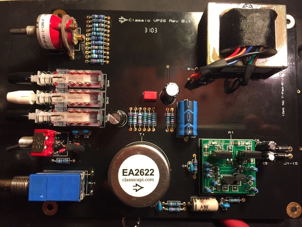
VP26_TOP_zpszlyvwden.jpg


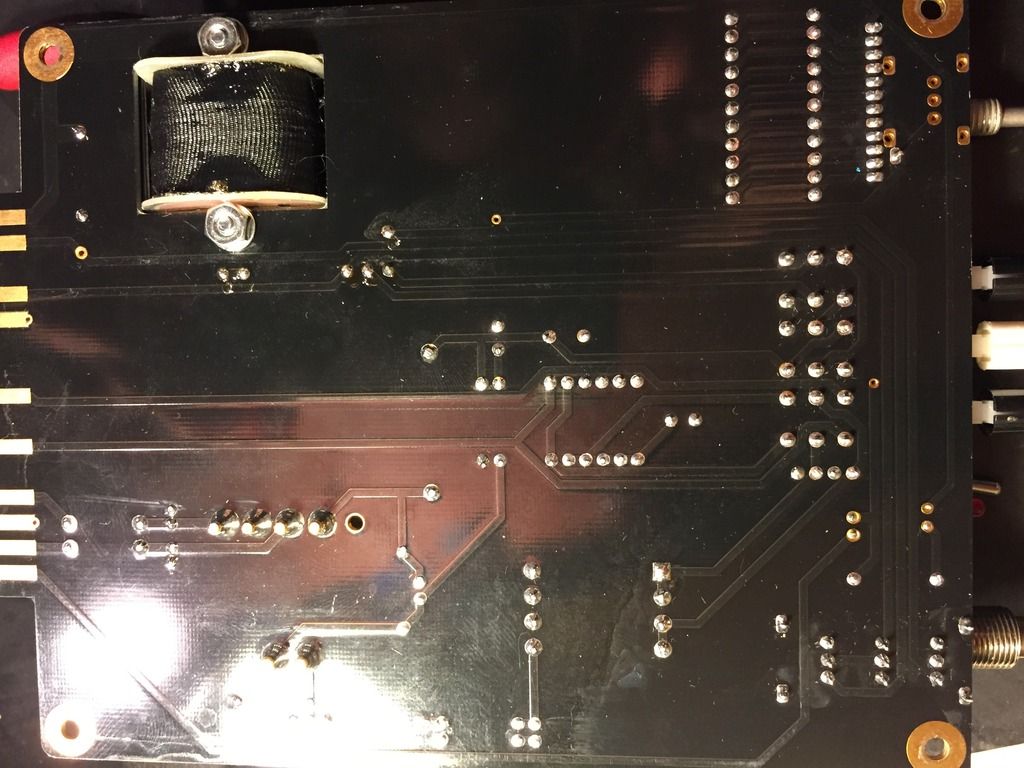
VP26_BOTTOM_zpsnpnmpld1.jpg
 
IndietownRecording said:
Hi, I'm having an issue with a VP26 I recently built.

The T-Pad output is least attenuated with the output knob in center position, with the output attenuation increasing as I move the knob left and right. It acts like the taper is wrong. It attenuates on both ends, and is loudest in the middle position.

The overall output is still really low, even at the center position.

I've double checked my transformer wiring and swapped out my opamp to a working SL2520 Red Dot.

Anyone have any ideas?
I would desolder the leads for the 2623-1 and check to make sure nothing is shorted. Measure DCR of each lead against all others and report which colors have resistance. All values should be less then 50Ω so set your DMM accordingly.
 
jsteiger said:
I would desolder the leads for the 2623-1 and check to make sure nothing is shorted. Measure DCR of each lead against all others and report which colors have resistance. All values should be less then 50Ω so set your DMM accordingly.

Thanks Jeff. Two questions: 1) should I measure resistance with the transformer leads in circuit? 2) should I apply power to the circuit when taking these measurements?
 
I will quote myself. Seems weird to say  :eek:

jsteiger said:
I would desolder the leads for the 2623-1 and check to make sure nothing is shorted. Measure DCR of each lead against all others and report which colors have resistance. All values should be less then 50Ω so set your DMM accordingly.
 
jsteiger said:
I will quote myself. Seems weird to say  :eek:

Ha! Super sorry. I wasn't getting a lot of readings on my DMM and was second guessing myself.

Here's what I got:

Red against Green = 14.5
Blue against Green = 23

That's it. The rest were 0.
 
jsteiger said:
I would desolder the leads for the 2623-1 and check to make sure nothing is shorted. Measure DCR of each lead against all others and report which colors have resistance. All values should be less then 50Ω so set your DMM accordingly.

Ok, so I just threw in a litz 2623 from another project, and the pre works normal. I just got finished putting the EA2623 back, and I'm back to the same issue.

Sounds like a bad transformer.
 
Well, with the measurements on a 2623-1 you should expect something like this;

Red-->Orange=14.5Ω
Blue-->Green=23Ω
Brown-->Black=23Ω

Make sure no leads are touching each other when taking the above DCR measurements. You should have an open reading or no resistance on any combinations EXCEPT what is shown above. My meter reads "OL" in this situation.

0Ω tells me its a direct short which is very opposite of open or OL.
 
jsteiger said:
Well, with the measurements on a 2623-1 you should expect something like this;

Red-->Orange=14.5Ω
Blue-->Green=23Ω
Brown-->Black=23Ω

Make sure no leads are touching each other when taking the above DCR measurements. You should have an open reading or no resistance on any combinations EXCEPT what is shown above. My meter reads "OL" in this situation.

0Ω tells me its a direct short which is very opposite of open or OL.

You're right, I misinterpreted my meter. I'm getting no resistance on all combinations except:

Red-->Orange=14.5Ω
Blue-->Green=23Ω

Brown-->Black=no resistance. I made sure that none of the leads were touching to eliminate the possibility of any shorts.

Do you think this means the transformer is bad?

 
IndietownRecording said:
Red-->Orange=14.5Ω
Blue-->Green=23Ω

Brown-->Black=no resistance. I made sure that none of the leads were touching to eliminate the possibility of any shorts.

Do you think this means the transformer is bad?
Yes indeed. Please send me an email and I'll take care of sending you a replacement.
 
rshake87 said:
Hi guys! I too have the green light problem happening. When I power up the unit, it passes signal perfectly with good tone, however the green light stays lit until the gain knob is turned to the center position. It then turns off and functions normally. Is there any way to remedy this? Thank you.

Hey Jeff and everyone else,

I too am experiencing a similar problem on a new build. I searched, but was not able to find any responses to this problem.  The green signal led stays lit when I first power up the module, but strangely, when I turn on phantom power, the signal led functions as normal. Turn phantom back off, the signal led goes back to constantly lit. Another odd behavior I have noticed is that around 30 minutes of use, the signal led begins to function as normal, regardless of the 48v phantom switch position. Kinda stumped on this one. Everything looks like its correct. Signal passes fine and the preamp sounds fantastic.

Things I have tried:
    Changing the op-amps for known working op-amps.
    Reheating connections that are in the path.
    = Same behavior.

Could this be a faulty chip? What would cause it to function normally once heated and running for 30ish minutes?

Note: I do have plenty of experience with electronics, worked with Keeley Electronics for years. Still stumped. Any help is appreciated.
 
I do agree, however, this thread had someone posing the same problem I had. I can post again, or the mods can move my post. Whatever we think is best.

Just looking for some answers.
 
Hi guys!

I've build hundreds of VP26s by now, and probably nearly as many VP28s, as well as a handful of other CAPI preamps and modules.
In the past I've had only a handful of issues, every time it was either faulty input or output transformers.

I recently built a set of 4 VP26s with SL2520 red dot op amps and Litz output transformers.  3 of them sounded perfect but one has VERY low signal output.  When I attach a mic I do get signal, but it's far too low in level.  I have tried various mics and slots in my chassis and there is no issue with the mic/cable/chassis, it is definitely something with the VP26 itself.

I have quadruple checked each component (there aren't that many) and am positive that there is no build error.  I also tried de-soldering the Litz output transformer leads and checked the windings.  Cross checking the Litz data sheet I only see resistances between leads of the same windings, so that looks good.  That's about as far as I have gotten in troubleshooting.  I could de-solder the input transformer but that is quite a bit of work.

I do have a decent digital multimeter, a function generator and also the extension jig (that I got for building/tuning VC528s).  I can inject a signal and measure it at points using my DMM.  Is there are place in particular that I should try?  Any help here would be great!

MZ 
 
The best way to proceed and find out where the problem starts is to inject signal and "follow" it thru the circuit with an audio probe, a scope or DMM set to ACV.

I would inject a 400Hz tone at -40dBu. You will have to use the schematic as a "road map" of sorts probing along the way to see where the first large difference shows up. The good news is you have 3 good units to get some benchmark readings from. There are really only a few spots to check. I do publish the schemo for this preamp so everything you need is on there.

First would be the 1k R. Pick an end and stay consistent. This is just after the 2622 input so differences here would point to the 2622.

Next would be at the 470µF coupling cap. Differences here would likely indicate the opamp but could also be something with the output transformer. Swapping opamps around would rule those out.
 
Jeff,

I've got things set up now.  I am using SL2520 red dots for these so I assumed there would not be an op amp issue... Just to be sure I took swapped op amps from one of the working units, no change.

I next injected the AC signal as you described (though I'm not positive of the input signal level from my function generator). 

I first checked at the R3 1k position.  Both good and bad modules read the same ~22mV.

Then I moved onto the 470uF coupling cap C10.  I tried checking both sides of this cap, and here I noticed a slight difference.

On the good module I see the same ~22mV on the negative side, but ~28mV on the positive side.

On the bad module I see ~22mV on BOTH the negative and positive side of C10.

Any ideas on what could be going wrong?
 
OK I've got an update.

I poked around both the good and bad VP26s some more and found some interesting things.  I had to reset my function generator as the last time I ran these tests the good unit was clipping.  Here are the test points and values I measured in VAC with my DMM (admittedly not the nicest DMM fyi)

GND=R14 (bottom)
                                          Good Bad
In High (J1-10) 11.7mV 11.7mV
In Lo (J1-8)       11.6mV         11.7mV
R11 (top)                 11.4mV 11.6mV
C10 (pos-bottom) 4.2mV     4.0mV
C10 (neg-top)         4.2mV             4.0mV
Out Hi (J1-2)           5.1mV     3.0mV
Out Lo (J1-4)           1.8mV   3.0mV

Here's something else that's interesting, when I use the phase invert switch on the bad unit all signal cuts out.  When I do this with the good unit the signal level doesn't change.  The mute switch works in the same way on both units as does the pad switches and phantom power settings have no effect on the signal.  Seeing the exact same values on Hi and Lo outputs for the bad unit seems strange, like there could be a phase problem with the differential outputs. 
Would this mean there is wrong with the output transformer?  I did desolder those leads once already and checked for shorts or open circuits in the windings.  Everything looked OK to me.  There were low DC resistances between leads of the same winding, and open circuit to the leads of the other windings.  Still at this point I'm not sure what else it could be?
 
I haven't gotten a response here in a little while.... but I did just get some new parts in and tried swapping out the output transformer for a new one.  Still no dice, same behavior.  I would love some advice on what to try now, I'm stumped as to what could be going wrong here...
 
From what you have posted, the audio levels seem extremely low on both units. It may be a DMM thing. Possibly rigging up a probe so you can "hear" at the test points may be a better way. Either that or get a good Fluke with true RMS.

The fact that the signal cuts out completely when engaging the polarity switch is a problem. That makes me think bad solder joint at the switch, bad switch, problem with the t-pad or output transformer. By looking at the schematic you can see exactly whats happening when that switch is depressed. It is simply swapping the primary leads of the output transformer.

You can easily lift the output leads from the secondary of the transformer and check the output there. This will bypass the t-pad.

Maybe probe the pins on the polarity switch to make sure both poles are making proper contact in both positions.
 

Latest posts

Back
Top