[BUILD] GIX-51X tube preamp

GroupDIY Audio Forum

Help Support GroupDIY Audio Forum:

This site may earn a commission from merchant affiliate links, including eBay, Amazon, and others.
Very very cool, kvothe!

bruce0, I'm wondering if there's any benefit in trying to measure distortion (due to RF noise clipping at high gain) in a shielded VS unshielded DC converter. That would be the only audible symptom of converter switching interference on the input transformer.

 
gemini86 said:
I'm wondering if there's any benefit in trying to measure distortion (due to RF noise clipping at high gain) in a shielded VS unshielded DC converter. That would be the only audible symptom of converter switching interference on the input transformer.

The converter radiates EMI noise at about 110khz (using the inductor size specified) and I don't know what you mean by about RF noise clipping.  That 110K Hz signal can be detected in a transformer near the source, and has low order harmonics in the audio band.  The Cinemag (and the Andersen) are round and thus pretty far from the source (and shielded well) and I think very well protected from that signal. The lundahl not so much, it is closer to the inductor.

I imagine that the noise difference I detected (which is less than 3dB) is some low order harmonic of the 110K because my testing is only from 20 - 20000.  The difference in noise level is apparent in the summaries, but finding a 3db peak is pretty impossible it is lost in the noise of the other self noise of the preamp.

What I heard without the little foil shield was a low frequency hiss at very high gains (A sort of hiss with a rumbly sound).  This reduced when I put on the shield.  I could measure it, but I could not see it on a frequency distribution.

In summary I don't think shielding is worth much (except possibly with the Lundahl input trafo which is 3 times closer to the PSU inductor).
 
I think what I meant was (sorry, a bit sleep deprived) that the input headroom may be decreased because of the switching noise bleeding into the first stage and being amplified, kindof like a parasitic oscillaiton. The feedback network should remove this though, so I guess it's probably not a problem. Leave it to me to start a wild goose chase. I also guess I didn't realize (or had forgotten, more likely) that you had detected some sub harmonics from the switching supply in the audible range. My future designs are going to feature an EMI/RF shield on the main board to protect against these problems.
 
I don't think it is a problem.  My test procedure was wrong and when I fixed it the noise was minimal.

My GIX51X are just as quiet as my G9 channels with the external PSU (actually quieter at the moment <grin>).
 
Hey guys,
I still have the problem that my GIX-51X pre does not amplify as it should. I did some listening test with dynamic mics and condensor mics through XLR input and bass or keys through the DI input and I still have very low gain. I can hear the signal, there's no lack of bass or treble and the sound seems o.k. The gain switch is working (it increses gain in steps when turning it cw) and the output pot is working, too. The problem is that I have to really crank up gain to get a half-decent output level. Other members wrote that the preamp has lots of gain.

First thing I checked was the HV board. It puts out 242V so that is o.k. I think.
Heater voltages are o.k. and tubes are glowing nicely. So today I finally had a little time to check the HV directly on the tube sockets.

With my lab-psu on +/-24V connected to the pcb my measurements directly at the tube sockets were:

V1 - pin 1: 82,7V
V1 - pin 6: 158,4V
V2 - pin 1: 5,35V
V2 - pin 6: 235,2V

Measurements taken with a DMM between psu ground and the respective tube pin.
Are those voltages o.k. I was a little surprised about the deviations.
But I'm not that familiar with tube circuits.

Any ideas?
 
Here were go:

V1 pin 1 - 82.7V
V1 pin 3 - 2.16V
V1 pin 6 - 158.4V
V1 pin 8 - 74.5V

V2 pin 1 - 5.351V
V2 pin 3 - 2.78V
V2 pin 6 - 235.2V
V2 pin 8 - 14.24V
 
Sorry benny, let me clarify.

We need anode, grid and cathode for all 4 triode sections.

V1:
1 -
2 -
3 -
/
6 -
7 -
8 -

V2:
"etc."

I'll try to help later tonight after work.
 
Okay...

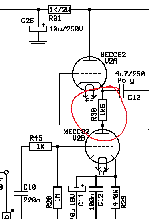
Right off the bat, V2, pin1 is a problem. Check that you didn't stuff the wrong resistor in R30. Should be a 1.5K, but maybe you accidentally used 150K? Although, if that were the case, you the cathode voltage on that section would be much lower. hmmm...

J12EZp5.gif


Have you swapped tubes yet?
 
Hi Rodney

I have already swapped tubes and tried differend brands, too. but that changed nothing. Gotta check the cathode and grid voltages later that evening.

Cheers
 
Here are the voltages after 5 minutes warm-up.

V1 pin 1- 82.7V
    pin 2- 0V (actually a few mV)
    pin 3- 2.16V
    pin 6- 158.4V
    pin 7- 35.8V
    pin 8- 74.5V

V2 pin 1- 5.35V
    pin 2- 5.36V
    pin 3- 2.78V
    pin 6- 235.2V
    pin 7- 5.36V
    pin 8- 14.24V

I'll check for wrong resistors tomorrow.

 
Are these static, everything at zero voltages?

Benny said:
Here are the voltages after 5 minutes warm-up.

V1 pin 1- 82.7V <--This seems low
    pin 2- 0V (actually a few mV)
    pin 3- 2.16V
    pin 6- 158.4V
    pin 7- 35.8V
    pin 8- 74.5V
<--The grid is 38 volts lower than the cathode...this triode is just about in cut-off mode, which greatly reduces gain

V2 pin 1- 5.35V <--Should be around half to 1/3 of supply voltage, I think. Can't remember exactly right now.
    pin 2- 5.36V <--Should be zero
    pin 3- 2.78V
    pin 6- 235.2V
    pin 7- 5.36V <--Should be same as pin 1
    pin 8- 14.24V <--This indicates a drop of almost 9 volts across R30, which is much too high. R30 may be too large, or the current going through it is very high.

I'll check for wrong resistors tomorrow.

I would check for wrong resistors, but also look VERY closely for solder bridges between the pin sockets, as it's very easy to have happen. The fact that voltage on pin 1 and pin 2 of V2 are the same tells me that this may be happening.
 
I haven't received any indication since the last bom update that there is any problem with it. It's the mouser carts that are unverified as of yet.
 
gemini86 said:
Yes.

Cathode (marked end) up. It's keeping voltage spikes from going back into your +24V supply.

So the side with the gray stripe pointing up correct?
 
gemini86 said:
I would check for wrong resistors, but also look VERY closely for solder bridges between the pin sockets, as it's very easy to have happen. The fact that voltage on pin 1 and pin 2 of V2 are the same tells me that this may be happening.

I checked R31 and R30 and their values are correct. But I found out that, while soldering test wires to the tube sockets, I must have accidentally shorted pin 1 and 2 on V2. So I cleaned it up and checked the voltages again:

V1 pin1 - 83.2V
    pin2 - 0V
    pin3 - 2.24V
    /
    pin6 - 161.4V
    pin7 - 38.18V
    pin8 - 77.5V

V2 pin1 - 78.1V
    pin2 - 0V
    pin3 - 1.84V
    /
    pin6 - 241.3V
    pin7 - 78.1V
    pin8 - 84V
 

Latest posts

Back
Top