Ptownkid
Well-known member
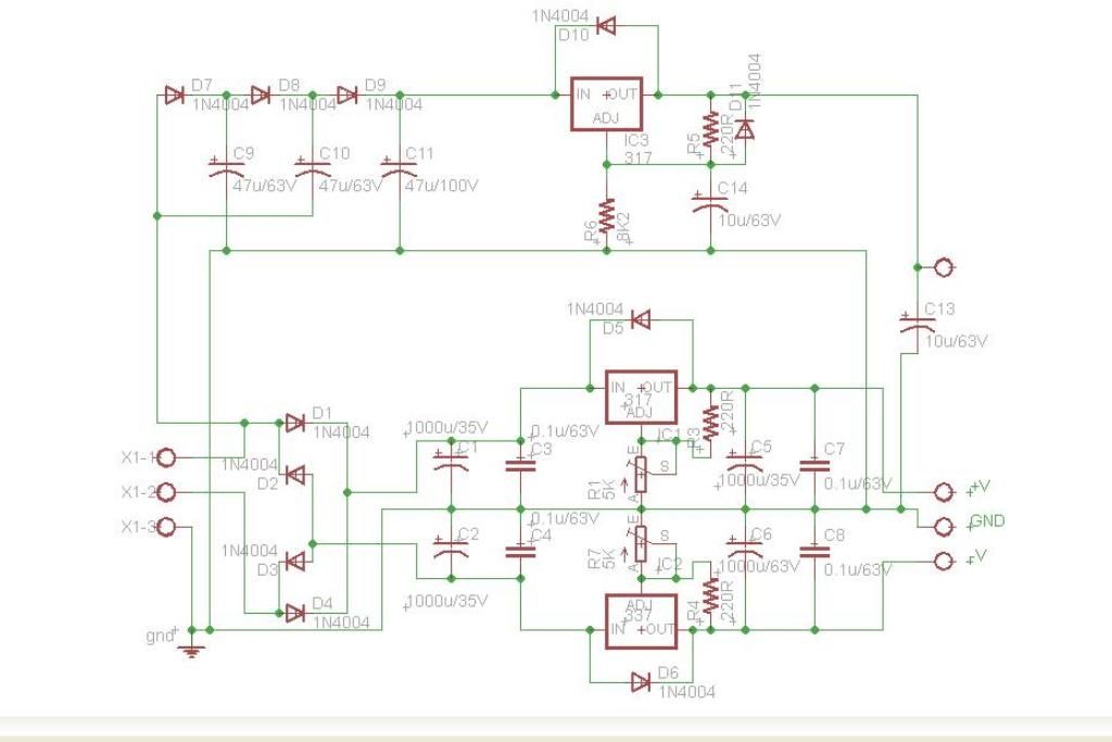
I've been receiving many e-mails lately for tips and advice on building the Psuniversal so I figured I'd put together a build thread to address some of the questions. This PSU is capable of delivering 2 rails of positive voltages and one rail of negative voltage. One of the positive rails is set to +48V for phantom power via an 8K2 resistor by you could change this by simply switching out that resistor if you had the need for some other voltage. The other two rails are adjustable. The current capabilities are decided by the VA rating of the power transformer you choose and the regulators, which are good for delivering about 1.5A continuously but be aware that the use of heatsinks may be required if you are powering more than a handful of modules.
Kits available here
All the components on the pcb are labled, but some will be hidden once the parts are populated. Here are the relevant docs
Schematic
Overlay
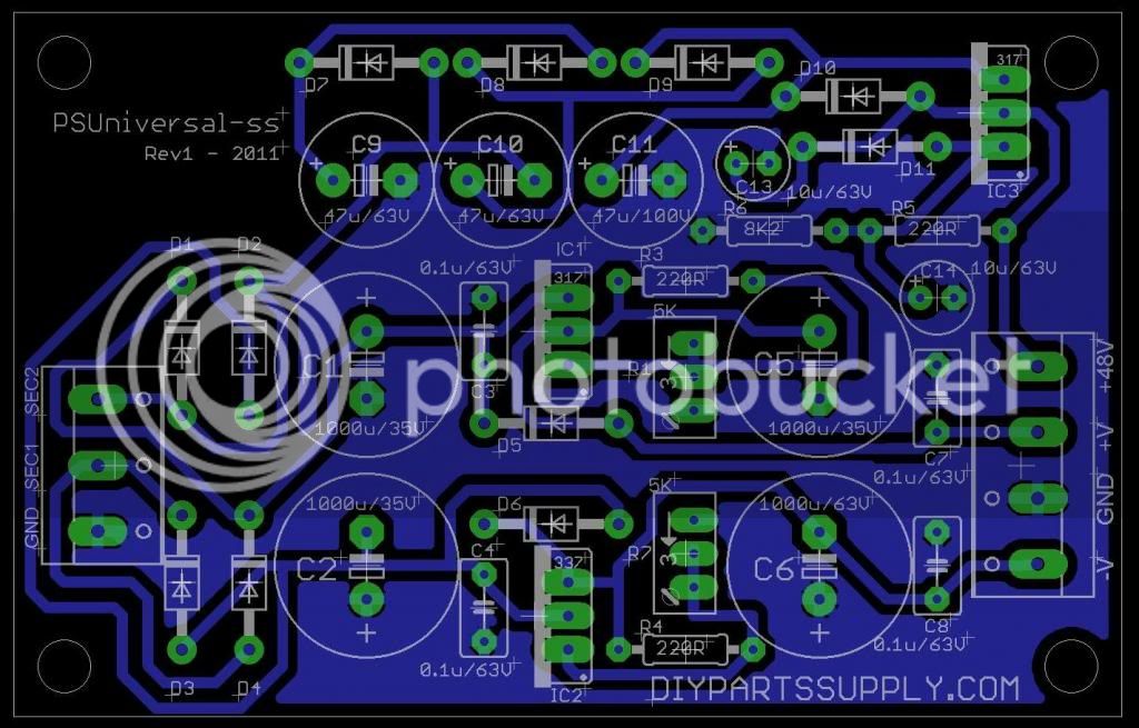
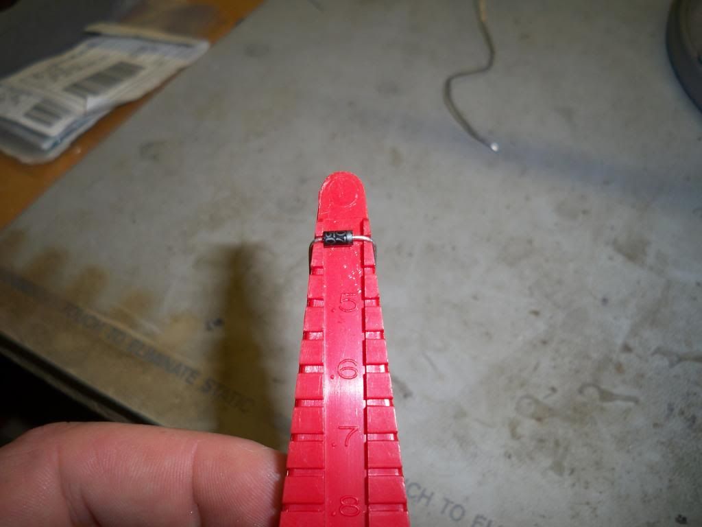
As with any pcb, the order in which you stuff components should be based on size if at all possible. Start with the lowest profile parts first so that taller components do not make it more difficult to insert shorter ones later. In the case of this project, that will be the resistors and diodes. It is best if you use a lead bender. While not absolutely necessary, they make things neat and are very inexpensive. The resistors and diodes for this pcb are all 0.4" (10.16mm) spacing.
Bend diode leads to 0.4"
When inserting the diodes, pay close attention to which way the cathode faces. On the diodes it is represented by a thick band and on the pcb by a thick line. On this pcb they all face either left or up.
Insert all diodes
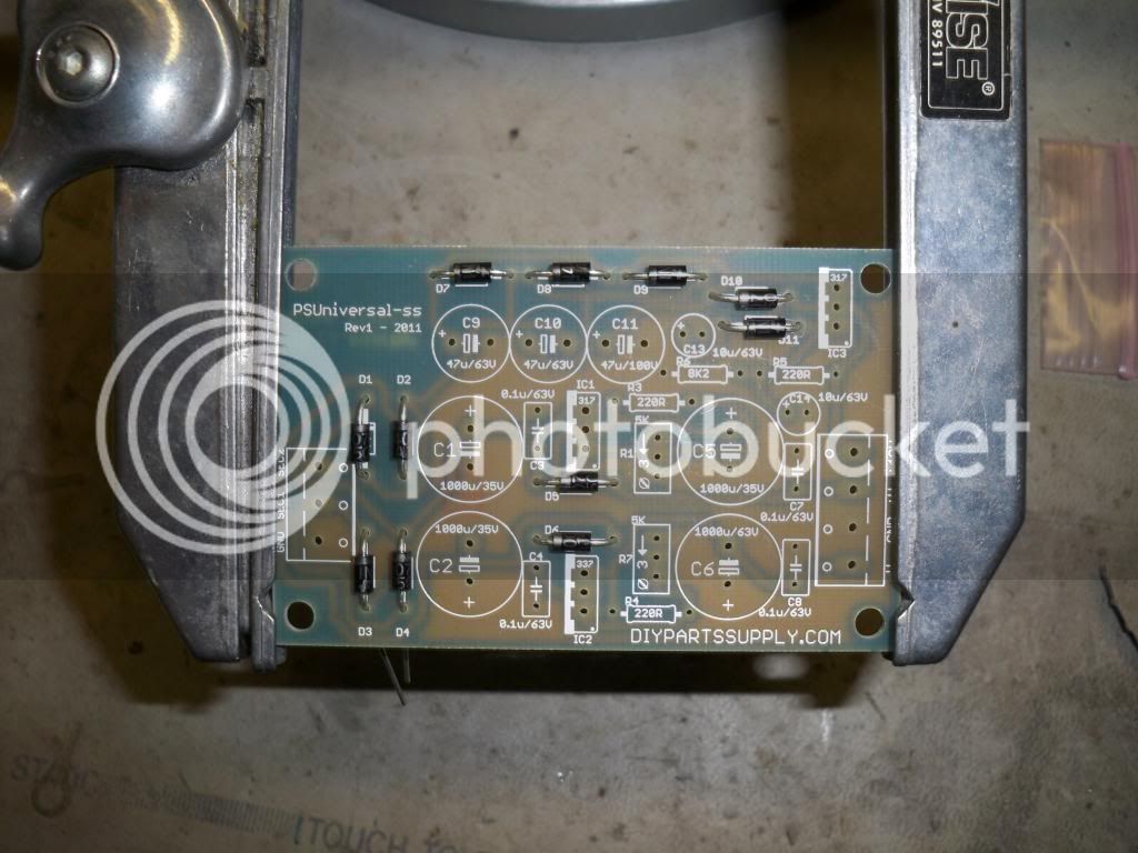
I like to avoid adding too many components at once so now is a good time to solder the leads and clip them. If you get too many components inserted at once, it makes it very difficult to maneuver your iron tip in to make good contact with the leads and pads. When soldering you should always try and touch the component lead AND the solder pad at the same time. Always touch the iron to the joint THEN touch the solder to the iron while still in contact with the joint. Not doing so can cause cold solder joints that will likely fail and are sometimes hard to find. A good solder joint should look similar to a volcano and be shiny.
Diodes soldered
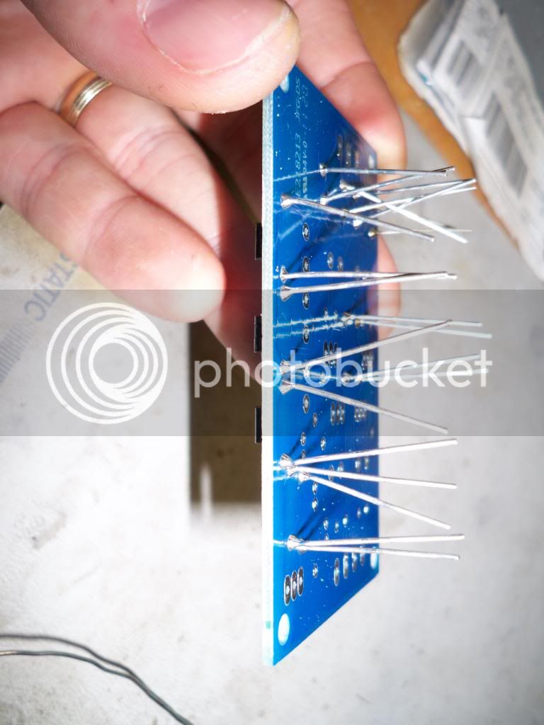
You will need to sort the resistors by either using a multimeter or reading the colour code. It may take a while to memorize and get good at it, but learning the colour code is highly recommended. In this case, there's only two values so it's very easy.
Bend resistor leads to 0.4"
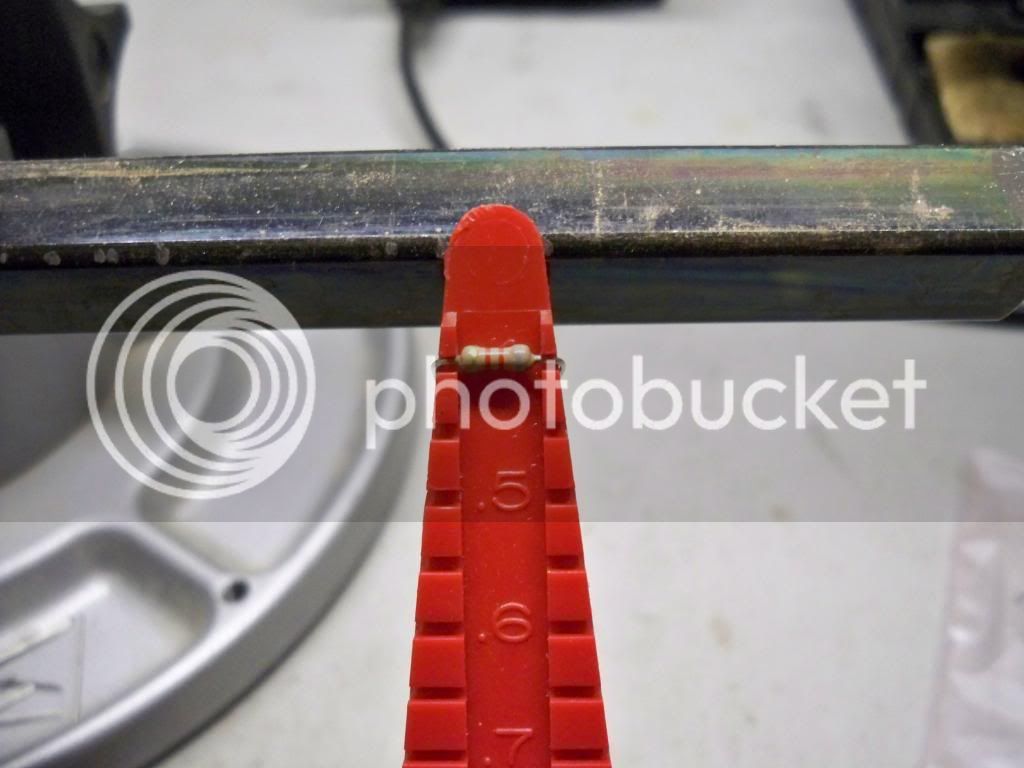
Insert all resistors and solder
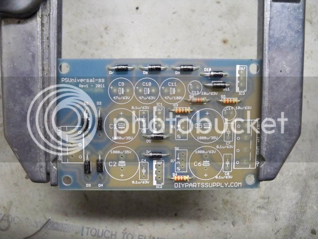
Next up are the 0.1uF poly capacitors, there are only 4 and they have no polarity. If you are having any problems getting them to stay when you flip the pcb to solder, you can gently bend the leads away from each other to make them stay steady for you.
Insert all poly caps and solder
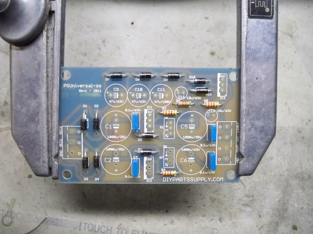
At this point I like to add C9-C11 and C13-C14 across the top of the pcb. These are electrolytic capacitors and as such they have a polarity. They are marked in several ways. The positive side is the longer lead, and the negative side is marked with a stripe down the side of the body. On the pcb itself, the positive is marked with a +. Attention needs to be paid to which way these parts are inserted. In the case of these five capacitors, the negatives all face to the right.
Insert C9-C11 and C13-C14 and solder
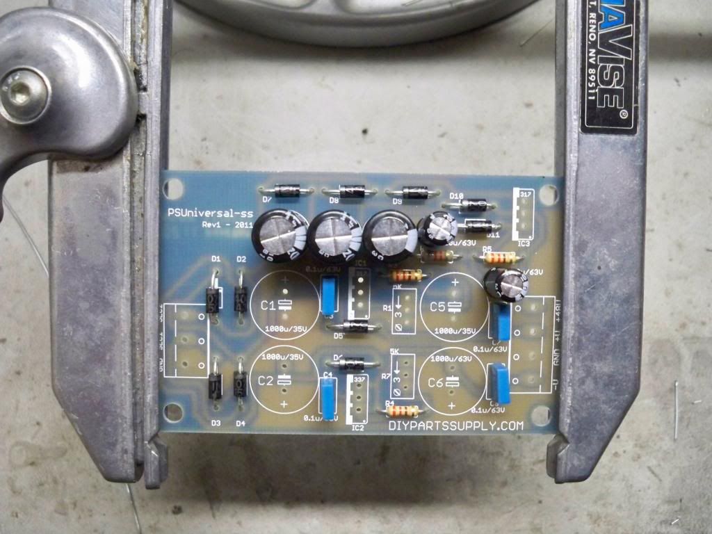
Now we come to the first of the larger electrolytic capacitors. At this point i only put C1 and C2 in so that I still have room to add the two voltage regulators and the trimpots. Alternatively you could simply add all four large caps after the voltage regulators and the trimmers. Again, pay attention to polarity. The negative face inwards towards each other.
Insert C1 and C2 and solder
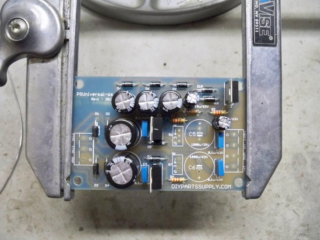
Time for the voltage regulators. There are two different kind, so please be mindful of putting the right ones in the the right place. The top two are both LM317's and the bottom one is a LM337. The metal tab on the regulators faces in the same direction as the thick line on the circuit board. IN this case they all face the tab to the left. I find it easiest to bend the outermost leads gently away from each other in order to hold the part in place while I solder the middle lead. Then I straighten the two leads and solder.
Insert voltage regulators

Bend leads gently, solder middle lead, straighten other leads, solder
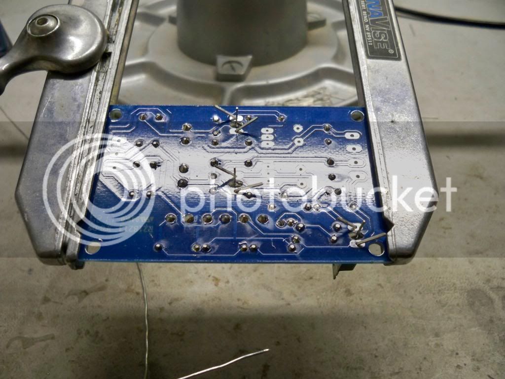
Next insert the trimpots. It does not matter which way these are inserted, but I prefer to keep the adjustment screw away from C5 and C6 making it easier to access. I also bend the leads gently to hold these in place while soldering.
Insert trimpots
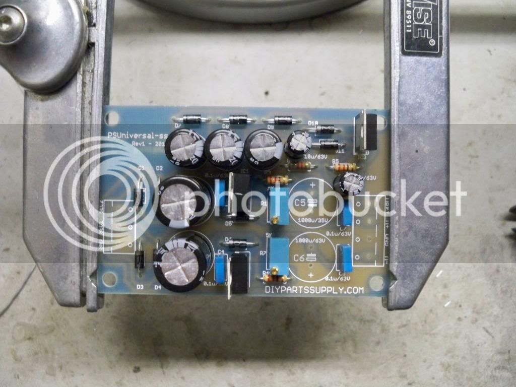
Bend leads gently, solder middle lead, straighten other leads, solder
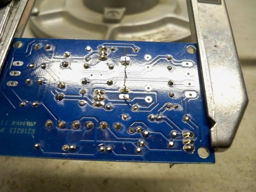
AT this point we can add the rest of the components. All that should be left are two electrolytic capacitors and two terminal blocks. Make sure to once again pay attention to which way the electrolytic capacitors are inserted, negatives facing each other.
Insert C4, C5, and terminal blocks and solder
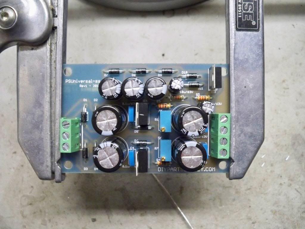
Once you've trimmed any remaining leads all that's left is to give the board a cleaning. I usually simply give it a quick scrub with some isopropyl and a fingernail brush, but there are specialty flux removers and pcb cleaners if your are so inclined. Take a minute to visually inspect all your solder joints and all your parts in case you've made an error while populating the pcb.
You should always test your newly built PSU by itself before using it to power something. Better to find out now that you've made a mistake or have a faulty part than to fry something else in the process. When hooking up your transformer to the pcb there are three connections to make on the input side. Sec1 and Sec2 are your transformer secondaries and are interchangeable and the spot marked GND is for your center tap. Before powering on make sure that your pcb is on standoffs or a non conductive surface. Adjust the trimmers to get the approximate voltage that you want (for the +/- outputs) but keep in mind you will likely have to adjust again once the PSU is in situ.
Cheers and have fun!
Kits available here
All the components on the pcb are labled, but some will be hidden once the parts are populated. Here are the relevant docs
Schematic

Overlay

As with any pcb, the order in which you stuff components should be based on size if at all possible. Start with the lowest profile parts first so that taller components do not make it more difficult to insert shorter ones later. In the case of this project, that will be the resistors and diodes. It is best if you use a lead bender. While not absolutely necessary, they make things neat and are very inexpensive. The resistors and diodes for this pcb are all 0.4" (10.16mm) spacing.
Bend diode leads to 0.4"

When inserting the diodes, pay close attention to which way the cathode faces. On the diodes it is represented by a thick band and on the pcb by a thick line. On this pcb they all face either left or up.
Insert all diodes

I like to avoid adding too many components at once so now is a good time to solder the leads and clip them. If you get too many components inserted at once, it makes it very difficult to maneuver your iron tip in to make good contact with the leads and pads. When soldering you should always try and touch the component lead AND the solder pad at the same time. Always touch the iron to the joint THEN touch the solder to the iron while still in contact with the joint. Not doing so can cause cold solder joints that will likely fail and are sometimes hard to find. A good solder joint should look similar to a volcano and be shiny.
Diodes soldered

You will need to sort the resistors by either using a multimeter or reading the colour code. It may take a while to memorize and get good at it, but learning the colour code is highly recommended. In this case, there's only two values so it's very easy.
Bend resistor leads to 0.4"

Insert all resistors and solder

Next up are the 0.1uF poly capacitors, there are only 4 and they have no polarity. If you are having any problems getting them to stay when you flip the pcb to solder, you can gently bend the leads away from each other to make them stay steady for you.
Insert all poly caps and solder

At this point I like to add C9-C11 and C13-C14 across the top of the pcb. These are electrolytic capacitors and as such they have a polarity. They are marked in several ways. The positive side is the longer lead, and the negative side is marked with a stripe down the side of the body. On the pcb itself, the positive is marked with a +. Attention needs to be paid to which way these parts are inserted. In the case of these five capacitors, the negatives all face to the right.
Insert C9-C11 and C13-C14 and solder

Now we come to the first of the larger electrolytic capacitors. At this point i only put C1 and C2 in so that I still have room to add the two voltage regulators and the trimpots. Alternatively you could simply add all four large caps after the voltage regulators and the trimmers. Again, pay attention to polarity. The negative face inwards towards each other.
Insert C1 and C2 and solder

Time for the voltage regulators. There are two different kind, so please be mindful of putting the right ones in the the right place. The top two are both LM317's and the bottom one is a LM337. The metal tab on the regulators faces in the same direction as the thick line on the circuit board. IN this case they all face the tab to the left. I find it easiest to bend the outermost leads gently away from each other in order to hold the part in place while I solder the middle lead. Then I straighten the two leads and solder.
Insert voltage regulators

Bend leads gently, solder middle lead, straighten other leads, solder

Next insert the trimpots. It does not matter which way these are inserted, but I prefer to keep the adjustment screw away from C5 and C6 making it easier to access. I also bend the leads gently to hold these in place while soldering.
Insert trimpots

Bend leads gently, solder middle lead, straighten other leads, solder

AT this point we can add the rest of the components. All that should be left are two electrolytic capacitors and two terminal blocks. Make sure to once again pay attention to which way the electrolytic capacitors are inserted, negatives facing each other.
Insert C4, C5, and terminal blocks and solder

Once you've trimmed any remaining leads all that's left is to give the board a cleaning. I usually simply give it a quick scrub with some isopropyl and a fingernail brush, but there are specialty flux removers and pcb cleaners if your are so inclined. Take a minute to visually inspect all your solder joints and all your parts in case you've made an error while populating the pcb.
You should always test your newly built PSU by itself before using it to power something. Better to find out now that you've made a mistake or have a faulty part than to fry something else in the process. When hooking up your transformer to the pcb there are three connections to make on the input side. Sec1 and Sec2 are your transformer secondaries and are interchangeable and the spot marked GND is for your center tap. Before powering on make sure that your pcb is on standoffs or a non conductive surface. Adjust the trimmers to get the approximate voltage that you want (for the +/- outputs) but keep in mind you will likely have to adjust again once the PSU is in situ.
Cheers and have fun!


![Electronics Soldering Iron Kit, [Upgraded] Soldering Iron 110V 90W LCD Digital Portable Soldering Kit 180-480℃(356-896℉), Welding Tool with ON/OFF Switch, Auto-sleep, Thermostatic Design](https://m.media-amazon.com/images/I/41gRDnlyfJS._SL500_.jpg)


