Building BX25 remote - need help reading schematics

GroupDIY Audio Forum

Help Support GroupDIY Audio Forum:

This site may earn a commission from merchant affiliate links, including eBay, Amazon, and others.

a_)_i

Active member
Joined
Dec 9, 2008
Messages
25
Hi,

I need some help putting together a remote for my AKG BX25 reverb unit.  I am not trained in electronics so don't really understand schematics:

BX25remote3_zpsee5d42c7.jpg


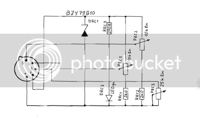
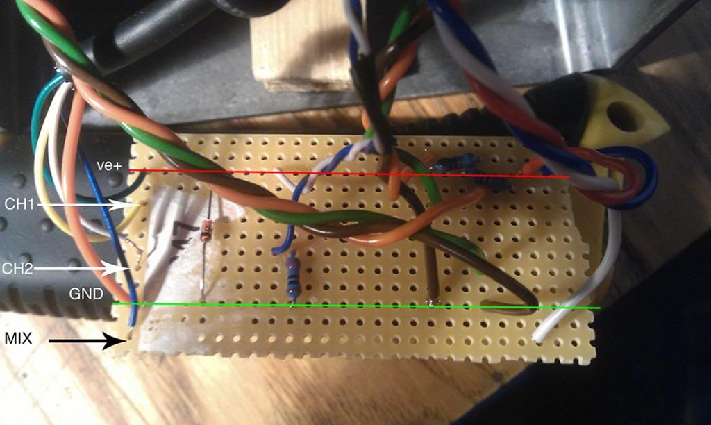
This is how far I have got.  When I pass a small voltage through this the LED doesn't light up but the 2 channel pots get the voltage and the wipers control the voltage sending back to the yellow and white CH1 & CH2 wires. The mix pot doesn't control voltage but I can't understand which parts to bridge.

The orange brown and green wires are for the two different decay potentiometers for CH1 & CH2.  Blue, red and white is for the mix control. 

When I turn the voltage up to around 1v my bench supply trips out.

BX25remote_zpsc387e67a.jpg

BX25remote2_zpsf94b1606.jpg


All advice welcome.
 
Swapped the diode around and that solved it.  Also had my LED the wrong way round too.

My interpretation of the drawing that if pin 1 was +ve. and 2 ground then the zener cathode would be connected to ground and LED cathode would be connected to +ve.  Could someone explain?

The final problem to fix is how to configure the 25k mix potentiometer.  Am I right in saying that the wiper and input 1 both come from the +ve. supply and are shorted together?  Then the connection to pin 3 comes from the remaining pot terminal?

Thanks for the help so far/
 
Now it is off the bench supply and plugged into the actual unit the LED doesn't work!  Switched it back the other way round now and it's fine.

The unit responds to the reverb/echoes control and the individual channel decay controls.  I'll put some pics up.

 
a_)_i said:
My interpretation of the drawing that if pin 1 was +ve. and 2 ground...
Wrong. Pin2 is positive in respect to pin1.

Am I right in saying that the wiper and input 1 both come from the +ve. supply and are shorted together?
No. They connect to reference voltage (what you call ground).

Then the connection to pin 3 comes from the remaining pot terminal?
Yepp, but the other way round. Voltage from Pin 3 connects to the remaining pot terminal and the varying resistance in the pot/rheostat shunts this control voltage to reference voltage by a more or lesser degree.
 
Hey,
I made a remote and it works fine, but one channel builds a feedback on its short RT!
It also happens when I disconnect the ground (pin1)!
Resisters are 1/4 watt by the way....
Thanks
 
The BX20 has a selection of trimmers that can cause this, when set wrong - probably also the case with the '25.

Try trimming/calibration procedure.?

Jakob E.
 

Latest posts

Back
Top