Analog_Fan
Well-known member
I was watching this video:
The power supply
design for my push pull amp experiment:

I had my focus on "fat" capacitors for the circuit itself and forgot that i also need capacitors behind the bridge rectifier and before the "regulator".
In the above video it talks about the Vdrop of the 7805 @ 2:37.
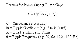
How would i apply the formula of this guy to find out the the values of the capacitors using the above mosfet circuit?
15V trafo after bridge rectifier = (15,4×1,4)−1,4 = 20,16V
If i would follow this guy:
input Volt: 20,16V - output V: 15 = 5.16V
2 x 5.16V = 10.32
using his formula:
(0,7×1,5)÷(10,32 × 50) = 0,002034884 F.
1,5 = the push pull circuit design target in Amp
Is this correct?
related to:
https://groupdiy.com/threads/a-darlington-type-audio-amplifier-idea.87389/
https://groupdiy.com/threads/amps-vs-pcb-track-width-using-to-220-package.87423/
The power supply
design for my push pull amp experiment:

I had my focus on "fat" capacitors for the circuit itself and forgot that i also need capacitors behind the bridge rectifier and before the "regulator".
In the above video it talks about the Vdrop of the 7805 @ 2:37.
How would i apply the formula of this guy to find out the the values of the capacitors using the above mosfet circuit?
15V trafo after bridge rectifier = (15,4×1,4)−1,4 = 20,16V
If i would follow this guy:
input Volt: 20,16V - output V: 15 = 5.16V
2 x 5.16V = 10.32
using his formula:
(0,7×1,5)÷(10,32 × 50) = 0,002034884 F.
1,5 = the push pull circuit design target in Amp
Is this correct?
related to:
https://groupdiy.com/threads/a-darlington-type-audio-amplifier-idea.87389/
https://groupdiy.com/threads/amps-vs-pcb-track-width-using-to-220-package.87423/


![Electronics Soldering Iron Kit, [Upgraded] Soldering Iron 110V 90W LCD Digital Portable Soldering Kit 180-480℃(356-896℉), Welding Tool with ON/OFF Switch, Auto-sleep, Thermostatic Design](https://m.media-amazon.com/images/I/41gRDnlyfJS._SL500_.jpg)


