


Matador
Well-known member
If I have a circuit like this:
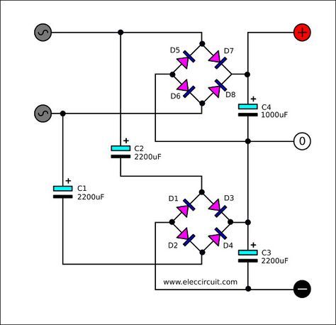
Does anyone know of a quick figure of merit for deciding how much DC current can be pulled from the negative rail, as a function of C1, C2, C3 size?
One way might be to figure out the equivalent impedance of C1 and C2 at mains frequency, to see what the AC voltage drop is across them. If I have a 3-terminal regulator after the bottom bridge, and I need 500mA of DC current, and I can tolerate no more than 5VAC drop across C1 and C2 (before my regulator goes outside of its minimum dropout), then C1 and C2 cannot be more than 10 ohms at 60Hz, which means the minimum size for C1 and C2 would be about 330uF (which is about 8 ohms at 60Hz). Would probably do 680uF to be safe.
(I get this isn't an ideal way to get a bipolar supply, however in my situation I'd like to have a completely floating secondary supply, that can be either positive or negative wrt. the first rectifier, which is why I'm capacitor coupling the second bridge so it's completely floating wrt. the first bridge). I'd also like to stick with a single secondary, since the current requirements of the second supply are only a few hundred mA at low voltages).


![Soldering Iron Kit, 120W LED Digital Advanced Solder Iron Soldering Gun kit, 110V Welding Tools, Smart Temperature Control [356℉-932℉], Extra 5pcs Tips, Auto Sleep, Temp Calibration, Orange](https://m.media-amazon.com/images/I/51sFKu9SdeL._SL500_.jpg)


