cap PSU for a Tori ??

GroupDIY Audio Forum

Help Support GroupDIY Audio Forum:

This site may earn a commission from merchant affiliate links, including eBay, Amazon, and others.

Freq Band

Well-known member
GDIY Supporter
Joined
Jan 5, 2006
Messages
608
Location
Electra City
Reading some older posts over at Headwize, some have agreed that all I need is ample capacitance....no other regulation.

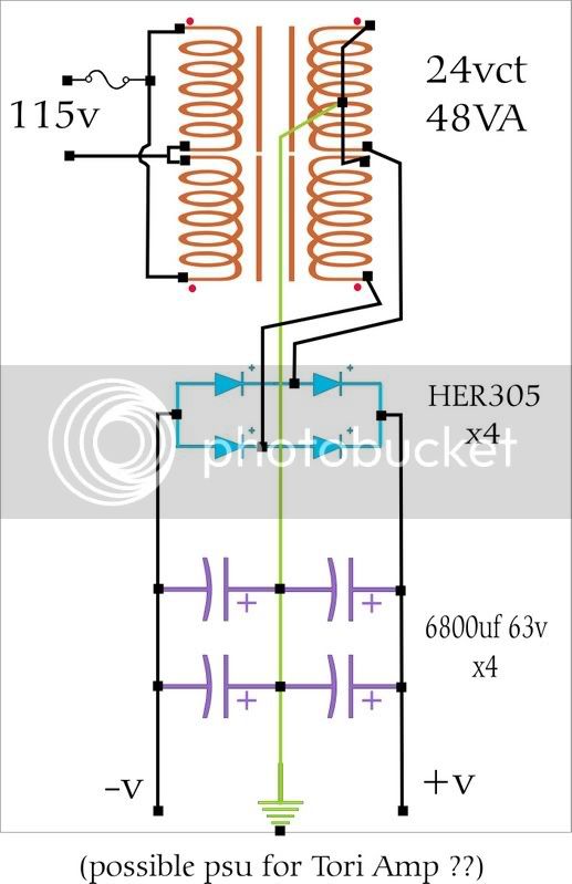
This is what appeared in my head -- from what was described (and from what parts I have now)....I'm not sure if I'm leaving something out.
Those secondary wires are meant to go under the tranny, not attatched to it's mid-point :cool: . In reality, I will not run them under the transformer.
Should I put in a resistor to eat some load, and to help discharge the caps at power-off ?
I am now thinking the tranny is too powerful.

Link to a Headwise thread (see last 3 threads:
http://headwize.com/ubb/showpage.php?fnum=3&tid=3930&srch=+tori+;

Link to the HER305:
http://www.diodes.com/products/inactive/category.php?category=a-h#

=FB=
Cap_PSU_draw.jpg
 
Hi FB,

The connections from the xformer to the bridge look wrong to me, though maybe the way it is drawn is confusing. For a bridge rectifier I think you would just connect the CTs together and leave them unattached, not to ground or the bridge. Then connect the legs of the xformer to the bridge to give you about 1.4 x 24, 34-ish volts unloaded or so into your smoothing caps. Using bleeder resistors won't decrease the voltage much, but if you use them in a CRC output it will decrease the voltage some and the noise too. That needs to be designed correctly to work right. I don't know how much voltage you are trying to get.

I hope this is right, somebody more knowlegable than I will most likely help out better. I wonder if RS still sells those nice little howto books, they had a great one about building power supplies.


Kiira
 
It looks to be drawn OK but not the way you might see in other schematics, look at the dots.


Did you ever fix your input problem?
 
Such kind replies !
....at least to my eyes.

I used schematic symbols, although in a "parts layout" fashion. I did not show that the caps-to-ground will be joined at a 'star' point.

I built it last night, although using a lower powered Xformer....24VA instead of 48VA. I also put a 100nf 250v cap across the output of the secondaries, before the rectifiers. I'll be using a commercial 115 line filter
before the Xformer. (If you care to point me to a proper link, I could build one myself, I've the parts I think.....or just tell me how (Gus, haha)).

It gives (+-)17.8 v on a 300 ohm load (test resistor).
I'd like to get it down to around 16v, as 18v is the 'stated' limit on most opamps I might be powering. I wil try a CRC filter, this weekend.
Would those filter parts be happy on my seperate (but same enclosure) Tori amp board?....I'm running out of room on the PSU board. (I have to find the proper {eek/way^+shun%} to determine CRC parts values.)
And that brings up.....the Tori has 1000uf caps-to-ground at the power input,.....the CRC before those....seem right?.......(Seems like there's uber capacitance pre-Tori, from this psu......or I might be missing the point of the tori's 1000uf's.)


Did you ever fix your input problem?
YES.
...that thread got "snipped" :? .....so I'll ask you again: I placed the resistance after the input caps.....Was this what I was supposed to see and fix ?

=FB=
 
ok, searching the web only confused me a bit more.
A cap-resistor-cap filter , in my psu.....would look like ?
....and is there a general value used, or these need to be calculated ??

?? is it....
my already installed smoothing caps (to ground)...
resistor in series after those caps...
small value cap-to-ground after the resistor ?

?? or, is it
a resistor in-series between the two smoothing caps?

=FB=
 
Hello, no...I'm not frustrated.
For the life of me, I cannot find, on the web, the way to calculate the proper values of Cap-Res-Cap low-pass filter for this PSU.
And I'm sure it's going to want me to know what the cutoff freq should be.
I don't yet know how to do that either. I think it is the standard ripple spike for my area.
DiyAudio, Pass Lab has the most info. but no clear explanation of how.
Duncan Amp has PSUdesigner, when I'm home I'll try that. (no internet there)
Google "CRC filter"....not much at all.
Lots on "RC" though. An automated RC calculator tells me 0.2 ohm R + 6800uf C gives me a roll off starting at about 117hz.....

=FB=
 
I have had a request for the long-lost ToriAmp schematic.

There was a MOSFET plan. It had troubles. The BJT plan works a bit better and much more stable.

No, it is not detailed. It was tutorial, not a build plan.

There is no reason to power headphone amps with +/-15V; +/-9V should be ample for almost any ear.
 

Attachments

  • Tori-Amp-NPN.gif
    Tori-Amp-NPN.gif
    5.2 KB

Latest posts

Back
Top