


ciscan.81
Active member

I have finally finished my first DIY preamp builds! By way of giving thanks to those who helped me in the DIY community I'd like to share my experiences and results.
Before I start I'd like to give my sincere thanks to Joe Malone at JLM audio for all his patience, advice and support right throughout the project. Not only does Joe design build and supply first rate DIY audio products; his after sales service is truly excellent. I really can't say enough good things about JLM Audio.
I'd also like to thank Jeff Steiger at Classic API of Illinois, Scott Liebers at Scott Liebers Audio, and Druedger at GroupDIY for their assistance and advice along the way.
Introduction
After a year or so of recording through my Digi 002R and its average preamps I reached the point in my humble home studio where I wanted to take a step up and introduce some nice preamps into my system.
After wide reading and research I settled on building the following preamps using kits I purchased from JLM audio:
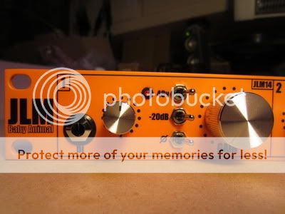
2 x JLM Baby Animals with variable input impedance, JLM14 input transformers (1:4 ratio), JLM99V opamps, JLM111 output transformers (1:1 ratio) (one channel with FET DI)
I housed these two units in a 1U rack unit leaving enough room to add another two Baby Animal channels in the future (probably 99V opamps with OEP input transformers).
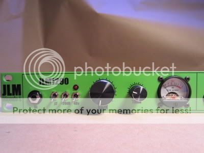
1 x JLM 1290 Macro with FET DI, dual range output trim pot (-5dB to 0dB or -90 to 0dB range with knob pulled out) and VU meter.
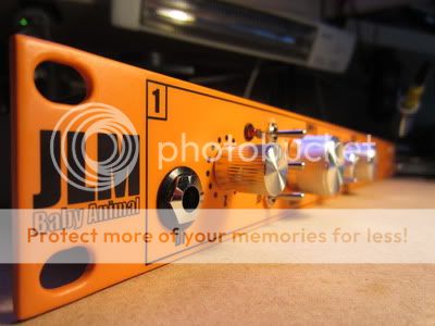
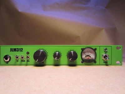
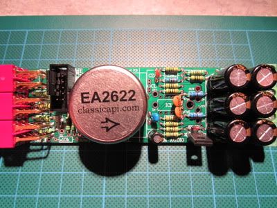
1 x API-312-style Baby Animal with variable input impedance, FET DI, EA2622 input transformer (1:7 ratio) (Classic API), SL-2520 'Red-Dot' opamp (Scott Liebers) and EA2623-1 output transformer (1:2 ratio) (Classic API), -15dB range output trim pot and VU meter.
This preamp is aimed at emulating the popular sound of the early 70's API 312.
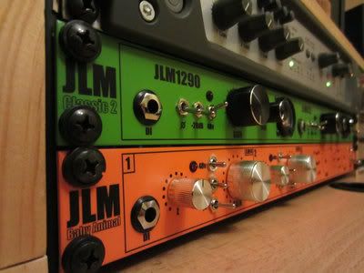
I housed these two more 'colourful' preamps in another 1U rack unit, I named the 'Classic 2'.
The two preamp racks share a 48v 40w 840mA SMPS power supply from JLM audio via a short daisy chain DC link cable.
Building the PCB's
Since this was my first DIY project I was a little daunted by the bags of electronic components that arrived (very quickly) in the post from JLM.
As most of you will know the Baby Animal PCB is cleverly designed to be very versatile, allowing preamps to but built using many different combinations of transformers and opamps. There are a few parts on the PCB whose value is dependent on these combinations and some that are left off altogether. While this is obviously brilliant for DIYers, it can cause a little confusion for the novice such as I!
Once I read through the PCB overlay and information on the JLM kit build threads, as well as taking a look at the printed PCB's in detail, things became a little clearer. While working systematically through soldering the parts onto the PCB it became apparent where everything needed to go. Although I did my best to educate myself, any queries and doubts I had along the way were very quickly and clearly answered by Joe through the kit build forum.
The Baby Animal's with the JLM14 inputs and 99V opamps were very straightforward to build as all the information for these was readily available on the JLM forums. The 1290 was also quite easy as there are no variations for this kit and the opamp modules come built and tested. The BA-312 style build, however, took a little more thought and research to find the correct values for the zobel network, variable Z pot, voltage regulator, output transformer wiring and output trim pot.
Below are the details for this build:
API-312-Style BA Build
- CL = NF
CZ - 220pf
RZ = 5k1 (this could be exchanged for 10k as recommended by Jeff at Classic API to give a slightly different frequency response, I'm yet to try this)
RL = 15k and 100k log pot
All opamp voltage parts marked # on the PCB were fitted to provide +16v to the opamp
Both 47pf Ceramic Capacitors on the PCB were replaced with 220pf
The values I used for parts that have less influence on tone like RGain, the gain pot, negative feedback resistor as well as a few caps are apparently not exactly what was used on the original API 312 but to keep things simple I just went with what was provided with the BA kit.
Output Transformer
EA 2623-1 output transformer wiring is as follows for 1:2 Ratio
- Primary 1+ (Orange) to BA +OUT
Primary 1- (Red) to BA 0v and XLR OUT pin 1
BA -OUT not connected
Secondary 2+ (Green) to XLR OUT pin 2 (via output trim pot)
Secondary 2- (Blue) to Secondary 3+ (Black)
Secondary 3- (Brown) to XLR OUT pin 3 (via output trim pot)
Output trim pot
The output trim pot I used was a dual ganged 1k log pot with a 820R shunt resistor.
Each side of the output transformer secondary (green and brown wires) were connected to pin 3 of each respective pot and then each wiper (pin 2) was connected to pins 2 and 3 of the XLR OUT respectively. After a bit of experimenting I settled on an 820R shunt resistor to give just a little more attenuation than the 1k pictured above (this was strapped across the two wipers [both pins 2], not sure if that was correct, but it worked ok)
Using the above method of output attenuation does change the output impedance, but when the connecting to a modern input like the Digi002R with a high input impedance of 10k or more it makes little audible difference, for a few dollars it does the job. Classic API have a 'true impedance' attenuator for about $30 that maintains 600ohm impedance on both sides if this is a concern.
Input Transformer
After some testing and deliberation I decided to go with the HIGH ratio for the EA2622 input transformer. With the LOW jumpers in place the sound was a bit fuller and smoother with more bottom end as compared to an aggressive mid-driven sound with the HIGH jumpers fitted. The latter I gather is a more characteristic 'Vintage API-312' sound, and I figured more useful as a contrast to the fat-buttery-smoothness of the 1290 and 99V BA's. In hindsight I could have designed in a pushbutton switch to allow easy switching between the two. This is still possible, but would ugly-up my front panel somewhat.
VU meters
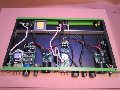
The VU meters and buffer kits ordered from JLM were very easy to set up. I simply stuffed the boards as the PCB indicated and soldered the VU meter solder tabs directly to the buffer PCB. I supported the PCB with a self-adhesive plastic stand-off and some double sided tape to isolate it from the rack case. As I was drawing the power for the buffer unit and meter LED from the 48v supply I used a 10K resistor in series for the V+ in to the buffer and also a 10k resistor in series on both the + and - legs of the LED to reduce the voltage.
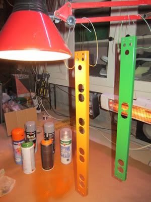
Front and Back Panels
Designing, machining and finishing the front and back panels for the preamps was a very time consuming process, but I am really happy with the retro-styled results. I certainly didn't save any money doing the panels myself; so if you just want a great sounding preamp relatively quickly just buy the premade panels and rack units from Joe, they are very reasonably priced.
I purchased the 1U rack units from Altronics for around $50 each. They are a good electronics supplier and ship Australia wide very quickly.
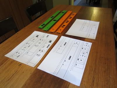
When designing the panels I had to be careful to allow enough room behind the panels for the various PCB's and pots to fit beside each other as well as within the constraints of the rack unit top and bottom. To ensure I hadn't made any mistakes with my measurements I mocked the panels up on some 3mm MDF and mounted all the completed PCB's, pots and other components. I did, however, forget to allow for the fixed 'nuts' on the inside of the panels where the top and bottom panels screw in. Luckily this only caused a problem with one DI PCB, which I was able to mount on an angle to get around it.
To design the layout and decals for the front panels I used a program called Front Designer 3.0 from Abacom, a German software company. This program is really easy to use and has a great wizard feature for designing scales for gain, Z, output knobs etc. The two shortcomings with this program are the printer calibration and the file export capabilities.
When printing from the program you are able to calibrate your printer to ensure accurate scale printing. Unfortunately this feature does not allow accurate enough calibration so I had to use a trial and error combination of zoom and printer calibration settings to get as close as I could to a true 1:1 scale. The method used for printer calibration in programs such as AutoCAD is much more accurate and user friendly.
Secondly the program can only export .PTL (HPGL files), which makes it difficult to get files read by a CNC router, water-jet or laser cutting machine should you choose to have them machined this way. Most CNC cutting businesses accept .DXF or .DWG files.
In the end it turned out to be too expensive to have the panels CNC cut anyway. Most CNC cutting businesses have a 'minimum charge' to setup and use the machines. The actual cutting was quoted at around $15 per panel, but the minimum charge was $80, not really very cost effective for two panels.
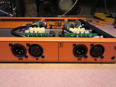
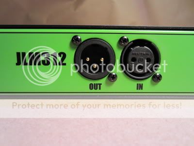
I opted to print a layout of all the holes I needed to drill using Front Designer. I glued this to the front panel using a paper 'glue-stick' and then carefully drilled out the holes using a drill press. This method worked ok for the smaller holes but it proved difficult to drill the 34mm holes accurately. For this I used a forstner bit and lots of lubrication as I couldn't find a hole saw in 34mm. For the XLR ins/outs on the back panel I used a 22mm hole saw.
Below is a table of the drill bit sizes for the various switches and pots:
| DI 11mm Pots (Gain, Z, Trim) 7mm 1290 Gain Pot 9.5mm Switches 6.5mm 48v LED 5mm Power Switch 12mm Power LED 6mm XLR IN/OUT 22mm XLR Screws 3mm DC Connector 8mm Fuse 13mm VU Meter 34mm VU Meter Screws 3mm |
Once they were machined and cleaned up I painted the panels with spray can etch primer and then enamel spray cans I bought for about $7 from the hardware store (White Knight 'Squirts' range). To finish I used a White Knight Crystal Clear Satin Acrylic spray can to give a matte appearance. Graffiti supply stores have a great range of colours in spray cans, but be careful to ensure compatibility with the acrylic clear coat. (I had trouble with a synthetic paint, and went back to the hardware store)
To apply the black text and knob scales to the panels I used clear inkjet waterslide decals. These are commonly used by model builders use to apply images to their models. I bought these on Ebay, for about $17 for a pack of 10 A4 sheets. They came with basic instructions for application. If you can find them and can justify the cost, 'Lazertran' decals are supposed to be the best.
I printed the designs from Front Designer using 'photo' printer settings and then sealed the decals with 3 coats of the clear acrylic to prevent the ink running.
I had to print the decals in two halves as they are too long to fit onto one A4 sheet. Front Designer has a function to do this automatically. This worked ok, but if you look closely you can just make out the join. If you can find them and are willing to pay the extra this problem could be avoided by using A3 decal sheets, cutting them down length-wise to fit into a printer and then using custom paper size settings.
It took a few attempts to get acceptable results with the decals but the following tips hay help:
- I Printed the decals with some marks (I used crosshairs) where the holes are to aid alignment
Use lint-free cloths! Bits of fibre and dust under the decals are a problem.
I used 1200 grit emery paper to ensure the panel surface was totally flat and free of dust specks and imperfections prior to applying the decals. (to do this you may need to many coats of paint to ensure you don't rub through)
I used warm distilled water to loosen the decals from the backing paper more quickly, you want them to just release and become moveable, not fall away completely.
I wiped the panels with a thin film of methylated spirits mixed with water (about 2 tbls to 1/2 cup water) prior to applying the decals to aid adhesion. (metho was recommended on the Lazertran website for this purpose)
I ran a thin film of pure methylated spirits along the edges of the decals and pressed them down firmly to prevent them curling up. The methylated spirits softens the decals if used sparingly but melts them if you use to much, so be careful!
Be sure to use firm pressure to carefully and thoroughly work the decal onto the surface of the panel and expel any water or air. I worked from the centre of the panel towards the edges, rubbing carefully but firmly with a lint-free cloth. Failure to do this will cause the decal to develop a cloudy appearance when it sets.
When fitting the switches, pots and LEDs through the panel be aware that the paint and decals will have made the holes smaller. To avoid damaging the finish around the holes (as I did) either carefully clear the paint from the holes using a drill bit or allow an extra half a millimetre where possible when drilling the panel holes.
Once the decals had set overnight I finished the panels with a few more coats of clear acrylic.
Drueger, a member of GroupDIY, who was very helpful to me and who's BA4 build inspired me to build my own rack cases has a good guide to waterslide decals here: http://www.groupdiy.com/index.php?topic=33839.0
Final Thoughts
I'm yet to do a full session with the preamps, but having had a quick mess around I am really happy with the sound. The 1290 is big, fat and buttery-smooth, with tight full bottom end. Loads of gain. So far I'm loving it on DI bass, you can drive it hard and then trim the output level with the really handy dual range output pot for a slightly fuzzy coloured sound. I'm keen to try this out on kick and vocals too.
The JLM14/99V BA's are solid, again buttery smooth like the 1290 but with less gain and slightly less colour. The variable Z gives a good range of tones. I'm sure these will prove to be a great all-rounder go-to pre, I love them already!
The BA-312-Style is much more aggressive mid-driven sound when the input ratio is set to high, I figure this will end up doing lots of work on guitar-cabs, snare and maybe some vocals on the right track. I haven't got an original API 312 to compare it to, but I am really pleased with how it turned out. With the variable Z and output trim pot I am able to dial in a wide range of colours. I'm still considering putting in a ratio jumper switch.
I saved a load of money building these pres myself, got a fully customised product with and learnt a lot about audio electronics along the way. I am really looking forward to filling out the other two slots in the JLM Baby Animal rack with my next builds!
")