Cavendish

GroupDIY Audio Forum

Help Support GroupDIY Audio Forum:

This site may earn a commission from merchant affiliate links, including eBay, Amazon, and others.
since the OP is sorted out i hope im not hijacking.
im about to put one in my gssl as well and i was wondering if any of you tried the different capi transformer options. their 2503 is available in stock, litz version and a nickel version. can anyone elaborate on the differences in sonics. would a nickel trafo improve things?
 
Good Evening folks,

I'm sure by now, you've all come to the conclusion that Keith and I disappeared into obscurity, and left y'all hanging in the wind with documentation updates and support on Cavendish.

Firstly, let me apologize. Yes, life has gotten busier for us both, and it's been tough even keeping up with orders at times, as real world jobs, and real world responsibilities keep piling on the "support needs".

Secondly, good news. Another forum member came to me asking about the dreaded pinout, and once that was resolved, how come the output was lower etc. Rather than update him directly, I decided to update the documentation, and update on our website.

We're up to PG1.1 of the board (have been for a while, without the docs to go with it!).
In short, the pinout challenges are actually on the GSSL board, and without knowing if they've resolved the difference between the schem and layout, it's tough to know which opamp in the NE5532 is doing what. Our documentation tries to resolve this, and give you the tools to find out which opamp is doing what.

You can find the new documentation on the link at the website:
https://expataudio.myshopify.com/products/gssl-cavendish-modification

Thanks again for your patience.

Rochey and Keith
 
hey,
i still struggle with this. i did everything according to the manual but can't reach unity gain. im missing a few db (like 3 or so) i was told by some forum members to replace the 27k feeding into the vca. but now the manual specifically says not to do so....
i replaced the input with the ic to make shure the output is the issue and it is. seems like im not the only one with this issue.
can you by any chance tell me what level i should have before my transformer off the cavendish board when feeding 0db to the input and not engaging the comp at all?
cheers

ps: can the 5k trimmer and resistor on the cavendish be changed to increase gain? my trimmer is all the way to 0 resistance already.

ps2: i use the 2503-l version. maybe i made an error there? i attached the two datasheets. i used the conversion table on the bottom of the 2503-l datasheet
 

Attachments

  • 2503-Litz-specs.pdf
    106.4 KB
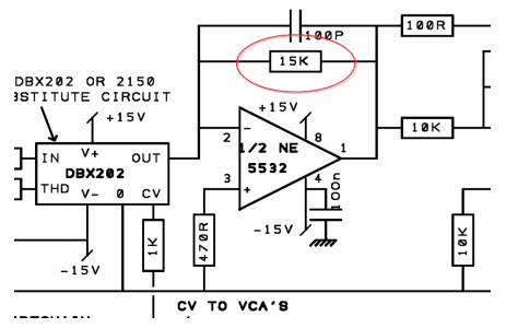
You mentioned you were using DBX202's and not the on board emulator, correct? The manual is says to leave the 27k's with the understanding you have a stock built GSSL board. I am using quad VCA adapters and I had to change the 27k resistors to about 15k (16.4k I believe). I hope this helps.

Thanks!

Paul
 
Potato Cakes said:
You mentioned you were using DBX202's and not the on board emulator, correct? The manual is says to leave the 27k's with the understanding you have a stock built GSSL board. I am using quad VCA adapters and I had to change the 27k resistors to about 15k (16.4k I believe). I hope this helps.

Thanks!

Paul

thanks Paul,
this helps a lot!
 
(second hand, I'll wait for Keith the comment for first hand data!)

The reason we don't touch the 27k is because we don't want to change the operating point of the VCA. Think of it as biasing.

SuDBBJl.png


I assume you've removed the feedback resistor on the main motherboard and are now only relying on the resistor and pot on the Cavendish board, right?

I believe that the equation for an current-to-voltage opamp configuration means that the higher the resistor in the feedback, the  higher the output voltage.  You might try (just for experimentation) changing the feedback resistor for something much bigger,  such as 10K or 20K. That should, in theory, boost your output voltage in the conversion.

However, I don't have a build to hand here to try that. (Keith has the design board). I've messaged him in the real world to get his feedback too.

Cheers

/R

 
Hey Rochey,
thanks for the reply. for now i replaced the 27k with 15k and it seems to work just fine. but if keith has a more elegant solution please let us know.
 
no i was wrong - sorry. i did not use the scope before now. and im pretty certain that the output transformer is to blame after all. please correct me if im wrong, but when measuring the transformers outputs (the molex output is left open so not connected to anything else) they are not balanced. one output is higher than the other. im a noob - but i guess this tells me that the transformer is wired incorrect? i used the conversion table provided by capi. maybe the other users who experience unity gain issues used the same trafo?
 
salomonander said:
... but when measuring the transformers outputs ... they are not balanced. one output is higher than the other.
Your transformer presents a floating balanced output. There is no relation to your GSSLs 0V reference voltage.
You measure output signal voltage between the transformers winding ends.
 
thanks harpo,
i dont think i do so. i dont have my scopes ground clip connected. just touching the transformers wires with my tip.
is that wrong? because i cant get that transformer wired. whenever i scope my outputs they are off. one line is alwys louder thatn the other. any other gear i test, gives me nicely balanced +-. im pretty lost atm.
 
..guess im just too dumb to scope a transformer. i wont bang my head against that wall no more :) im still left with a -3,9db drop when using the stock 27k into the vcas.
i found an original ssl schematic which uses 15k into the 202c vca as well as realizing that older gssl layouts used 15k as well. so i dont really see the issue. rochey?
 
Hey Salomonander,

Did you ever get this working right? I'm digging this up as im planning a Cavendish build, and wanted to use the 2503-Litz output trafo - but don't want to overcomplicate my life if it was causing issues. Thanks!
 
Resurrected! Hey all, i'm posting this with my members only jacket on as i'm late to the party by a decade or more as usual, I took the Cavendish idea a step further by fabroing my own pcb to drive the quad vca's in the Serpent SBA4000, using 6 Scott Liebers Red Dots in there, I haven't got it completed/hooked up yet but i thought id share the progress, gonna get it going using the 5532's and 5534's first and then jumper in the Cavendish red dots, I had to build the psu remote as i ran out of room in this guy(used an apex 460 tube mic supply box), i hope this ends up sounding half as good as the hassle😂
 

Attachments

  • IMG_5071.jpeg
    IMG_5071.jpeg
    1.4 MB
  • IMG_5072.jpeg
    IMG_5072.jpeg
    741.5 KB
  • IMG_5073.jpeg
    IMG_5073.jpeg
    703.9 KB
  • IMG_5074.mov
    5.6 MB
Back
Top