Cinema Engineering 7080 graphic valve eq schematic and discussion

GroupDIY Audio Forum

Help Support GroupDIY Audio Forum:

This site may earn a commission from merchant affiliate links, including eBay, Amazon, and others.

plumsolly

Well-known member
Joined
Nov 3, 2007
Messages
969
Location
Denver, Colorado
A while back, I bought a pair of Cinema 7080 equalizers sans power supplies or remote control panels. There is some information out there - the data sheet, a partial schematic and short discussion in the Audio Cyclopedia, and a short reference in a rane paper. I traced  the full schematic of the amp section. I believe what I have is correct, but if anyone notices any obvious errors, please let me know. My intention is to build a control section with rotary switches, which should not be too difficult. Attached is the schematic I drew up and here is a link to a packet of all the info I have: http://www.mediafire.com/?zkwyva4r2427j42

Thanks,

Ben
 

Attachments

  • 7080 schematic rev 1 small.jpg
    7080 schematic rev 1 small.jpg
    493.6 KB
Boy, it really made my day to see this post. I'm racking 4 of these, am running into issues, and just yesterday was trying (in vain) to find a schematic for the 7080 amplifier. With the tight construction, it must have taken you some time to reverse engineer the schematic. It will definitely be a big help to me, and I'll let you know if I find any errors.

The bad news is that what you're calling the control section is really the equalizer itself, and has 6 custom inductors. Not easy to duplicate! Will post some photos of it and it's insides later.
 
PRR said:
R1 R2 ratio can't be right.

Hey PRR - That's definitely what I have, but R1 is not original, which is most likely the problem. David, if you could look at your value for that, that would be great.

PRR said:
R29 seems oddly high for a power stage.

R29 is also not original . David, if you could look at that too, I would appreciate it.

David Kulka said:
Boy, it really made my day to see this post. I'm racking 4 of these, am running into issues, and just yesterday was trying (in vain) to find a schematic for the 7080 amplifier.

I'm glad - I think there will be a few people who will get some use out of this.

David Kulka said:
With the tight construction, it must have taken you some time to reverse engineer the schematic.

Yes - it was hassle!

David Kulka said:
The bad news is that what you're calling the control section is really the equalizer itself, and has 6 custom inductors.

I have the filter sections, thank goodness. I am just missing the control/slider section, which will not be too big of a deal to recreate. I haven't fixed on the way I am going to do this yet. The way to do it without spending a fortune on switches will be to use 12-pos Lorlins. I am leaning leaning towards using 9 positions for 8 1dB steps plus off, and a toggle for peak/dip. Other options would be using all 12 positions +  a center-off toggle for 2/3dB steps or 11 postions for 10 0.8 dB steps + off. It will partially depend on what kind of deals I find on switches. Grayhills or Elma would obviously be preferable, but 12 Elmas would stupid money.

I am in touch with another person who is recreating the control panel and someone else who has restored one and is really enthusiastic about the sound.

Best,

Ben
 
wow! also happy to see this post, ive got one of the control sections and ive been looking at maybe recreating the active part but i see its pretty much impossible to source all the iron on this...
 
I have updated a couple of component values on the schematic and I have a couple of questions.

What is the deal with C2? I don't have an exact value yet, but it is the 1-20nF range. Why only on the one stage? This is for low-end roll-off? Compensating for something? Transformer maybe?

I updated the values of C13 and C14. They are 10nF. Does this seems small?

Can someone explain the deal with R26 and R27? This is part of the bias arrangement?

I drew up a schematic of the remote control section, but I need to figure out the resistance values for each step. Is there a way to calculate these? Or does someone with a control section feel like measuring? Leadbreath?

Thanks, Ben
 

Attachments

  • Cinema 7080 Remote Control Schematic.jpg
    Cinema 7080 Remote Control Schematic.jpg
    322.1 KB
C2 is a treble boost if very small.  Probably to compensate for a loss somewhere. 

C13-14 doesn't seem small.  High frequency neutralization for a PP stage, I think.  Haven't seen it done that way exactly. 

R26-27 is a fixed bias arrangement.  Also not terribly common in small signal audio. 
 
> R26-27 is a fixed bias arrangement.  Also not terribly common in small signal audio.

Not really "small". Unlike an "amplifier", this is more a chain of +/- unity-gain stages working at fairly high levels for good S/N.

The +/- EQ is gotten partly by shunting cathode resistors. With simple self-bias this has little effect (maybe 5db boost at max).

Jacking the grids up to +10V "forces" larger cathode resistors, and lower nominal gain, but more increase-of-gain available via cathode shunting.

In an extreme case the stages are wired as Cathodynes with equal plate and cathode resistors, grids up around 1/4 of supply voltage. Then the L-C network is panned from plate to cathode to boost or cut, "swinging outputs". This plan seems to pan the EQ L-C from grid to cathode, "swinging inputs", which also works (of course).
 
Thanks for the points about the limits of self-bias here regarding cathode shunting.  I mean 'small' to mean an audio amp that isn't really in the power amp realm, passing a watt or greater. 
 
Thanks for the responses guys - that helps. Leadbreath is going to check his control unit for those resistances in a week or two. In mean time, is there a way to accurately calculate these values or does it make more sense to wire a rheostat in there and run some tests?

Thanks,

Ben
 
hey ben

ive got acces to unit now, if i understand u correctly u wanna measure the resistence of the inline fader? in my unit it the faceplate has in lines but the control knob is actually connected to 3 x 5k pots with a type of band and these circular "guides"?
unfortuneatley i cant post photos to show what i mean.

hope this helps

mick

 
Thanks Mick,

That makes sense, I think. They must have moved on to pots by the time yours was made - the data-sheet indicates steps. I think I'll have to wire it up and experiment to find the correct resistances.

Best,

Ben
 
I am still working on mine - I am really busy with school right now, so it is slow going. When I figure it out, I will post a full schematic.

Best,

Ben
 
I have been doing some more work on my 7080s. I built a temporary power supply and have been trying to work out the resistor values for the control section. I have made quite a bit of progress, and I have a few questions.

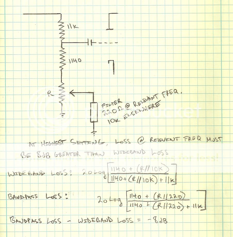
The attenuate section: I thought I could model this part as a simple frequency-dependent voltage divider like this:
Cinema7080LossCircuit.jpg
I got the impedance values by testing the filters in a circuit as part of a voltage divider. They seem to be consistant from band to band.
My equation for R looks like this:
Screenshot2012-03-18at64654PM.png
When I solve this, I get 4329.07 ohms. In my tests, however, 2.4k works right. So, questions: Is it ok to model this part like this, or is it more complicated? Have I done something wrong with my math? Assuming the 2.4k is right, any ideas on how to subdivide it for 1dB steps? Testing this is tough without something to go on, or 2.4k pot.

The boost section: I am getting consistantish values for the total boost control, 3.3k or so, but I think I need to get some new tubes before I can decide on a final value. What properties of the tube should be matched to for this purpose?

Thanks as always. I will post a full schematic of the control section with values when I get them all figured out.

Best,

Ben
 
Ok, I have made some progress since my last post. I got a more permanent power supply going using one of these: http://glass-ware.stores.yahoo.net/ps1kit.html I am real happy with it so far. I am still in the process of figuring out the control values, but I think I have a decent idea of what they should be. At the moment, I am trying to get to the bottom of a ~5db 55hz bump which seems to be present on both of my units. All the caps have been replaced, with the exception of the three 2uf oil can coupling caps, and the three 8uf (film?) caps that feed the boost controls. I tested the 8uf caps and they all read between 16-20uf. Do capacitors drift up in value? Does this indicate a problem? Anything obvious to check in regards to my 55hz bump?

On another note, I will need a couple of relays and leds when I finally get this thing going. I have 12.6Vdc for the heaters - can I borrow that? As it is, the heaters are elevated by ~75V. If I use the heater supply for my leds and relays, I would have to also use my heater "ground" (75V). Is there any problem with that?

Thanks as always,

Ben
 
I've done some probing around with scope and it seems like the 55hz bump comes in right around V2b. It's normal at the grid and has the bump at the plate. So there is something weird going on with the cathode of V2b, or some interaction with the inductance of the primary of the interstage, I guess. The only component change in that area was C2 was bumped up to .33, but I tried lower values and it didn't help the bump. I'm stumped. Any guesses?

Thanks,

Ben
 
Back
Top