Cinema Engineering Passive EQ - Pot Behavior Reversing with DI in chain

GroupDIY Audio Forum

Help Support GroupDIY Audio Forum:

This site may earn a commission from merchant affiliate links, including eBay, Amazon, and others.

nohatnoswim

Active member
Joined
Aug 4, 2010
Messages
36
Hi All,

I'm fortunate to have got 5 Cinema Engineering 4031B's in my life recently.
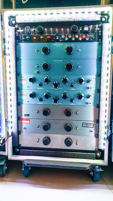
PSX-20200330-143241.jpg


I installed them and have found some strange behavior which I'm trying to debug.

When I got them, the cable ends were still in place indiciating where hot and cold had been before I got them:
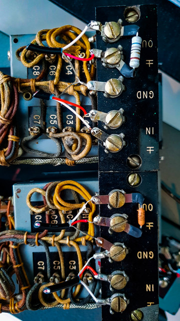
PSX-20200311-003040.jpg


So I installed them in the same way myself, with blue cable as my hot:
There are 2 types of connection board here, but old wires were on all so I just followed suit.
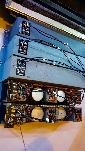
PSX-20200311-003249.jpg


When I patch them in on their own through my system in the following configuration, all is fine - they operate as expected with the gain loss.

Interface => Patchbay => EQ => Patchbay => Interface
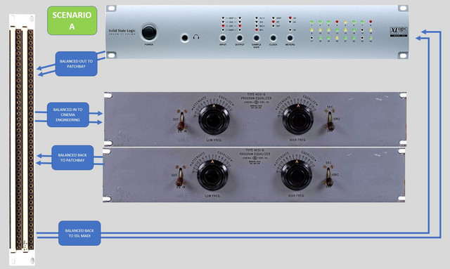
Scenario-A.jpg


However, when I add my DI's into the mix, the pot controls on the eq appear to reverse - eg  gain is cut, and cut is gain. 
I don't think it as simple as they are switched, they also seem to not be boosting and cutting as much as they should be either

Interface => Patchbay => EQ => Patchbay => DI => Patchbay => Interface
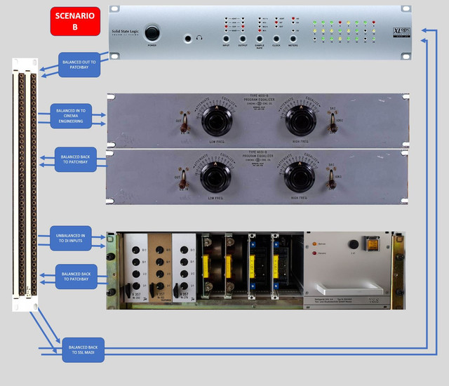
Scenario-B.jpg


I've considered that the previous cabling may have used white as hot instead of red - so I've possibly got them reversed - but I don't want to go pulling them out and re cabling just to check as it's a bit of a job to do it.

Doesn't seem to matter which DI's it's plugged into - they all have the same result.

They are a thing of beauty though I have to make up that gain loss to make them usable. 
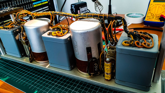
PSX-20200311-003423.jpg


Anyone got any thoughts on what's going on here ?

Thanks :)

 
I’ll see if I can replicate today.  Offhand that doesn’t make any sense.

Altec tech letter #192 goes through cases for loading, this filter does not need that load resistor, it's just causing more gain loss. 
 
EmRR said:
I’ll see if I can replicate today.  Offhand that doesn’t make any sense.

Altec tech letter #192 goes through cases for loading, this filter does not need that load resistor, it's just causing more gain loss.

Interesting - they were in place when I got the units so I kept them in place.  I'll pull them out so. Thanks !
 
gyraf said:
..you didn't swap input and output by mistake, did you..? I've had that with a G21 that was suspected to be really strangely behaving..

/Jakob E.

Interesting you mention that - I had a thought at one point during the installation that I may have swapped them around by accident and needed to validate but once I passed signal through it passed and I concluded that I had it the right way around - I'll double check that as there is a possibility that I've the IO backwards on the patchbay.
 
It looks to me like the inputs may have been wired incorrectly. I think the plus-over-minus symbol is an indicator of polarity. So the upper terminal is hot. Meaning just swap hot / cold on the inputs to match the plus-over-minus symbol. Just a guess though.

Note that because these are effectively two terminal in and two terminal out with no ground, they are effectively already quasi balanced. Meaning either side could be "hot" and it should not matter. But whichever is "hot" on the input has to match what "hot" is on the output. And right now it looks like they don't match.

Is there any documentation for these units? A quick google turned up nothing. A schematic would be ideal. But to really see if they're working properly you need to run white noise through them and look at the frequency response.

If you have the ability to check the response properly, you might also consider adjusting the damping resistor a little for critical damping. Right now it looks like it's 680 which, with a 10K load, sounds correct on paper. But it could easily turn out that you're knee is really blunt and you should go lower. Specifically, bring it down until you just barely start to get peaking in the high filter. It could easily turn out that you could go as low as 470R maybe (with the 10K load) before you reach critical damping. This is really important for a filter like this. It's what makes them useful.

Technically there might need to be a source damping resistor as well but it depends on the circuit. My 5 pole Allison Labs filters need them because the source 600 is part of one pole. Presumably these are only 18db/oct like the Pultec HLF-3C which doesn't need source damping. And in fact you would not want to because, even though it's designed for 600 ohm source / dest, the 600 ohm source would have no effect on response but would result in 6dB of attenuation unnecessarily.

CORRECTION:

Here is a link to a description of this unit:

  https://groupdiy.com/index.php?topic=63274.0

Apparently these are not high/low cut filters as I first thought. It looks like they're just basic low / high "boost" / cut. So some study would be required to determine what sort of source / damping would be required. I would DEFINITELY run some frequency repsonse tests starting with 600 source (or 500 maybe since all modern outs have something like 100 in series) and 600 load. That is what they're designed for. Then try removing / lowering to see what effect it has.
 
If the I/O is transformer balanced then the polarity of the In vs Out shouldn’t matter unless you are summing In to Out.  If it’s reversed they should null when summed. If there is no polarity reverse there should be a 6dB level increase when summed.
 
These are not transformer coupled.  They are the same as Langevin 251’s (first drawing in the Tech Docs) and Altec 9061’s and whatever the Hycor # is.  The classic Art Davis program EQ design.  Bridged T filters.  Manley also made a version for awhile. 
 
squarewave said:
So some study would be required to determine what sort of source / damping would be required.

None required, well documented in the Altec paper I mentioned.
 
EmRR said:
Altec tech letter #192 goes through cases for loading, this filter does not need that load resistor, it's just causing more gain loss.
I believe you mean the source resistor? Removing the load resistor would cause a massive peak.
 
squarewave said:
I believe you mean the source resistor? Removing the load resistor would cause a massive peak.

Just go read the paper. 


"response curves virtually unaffected by source and load impedances"

Corroborated by actual  measurements I've shown in another thread here somewhere. 
 
EmRR said:
Just go read the paper. 


"response curves virtually unaffected by source and load impedances"

Corroborated by actual  measurements I've shown in another thread here somewhere.
OK. Apologies.

But it also says "For smoothest response and ultimate attenuation, both source and load impedances should match the filter.". Those two things don't quite square. So I still would look at the response and see what different loads do.
 
squarewave said:
OK. Apologies.

But it also says "For smoothest response and ultimate attenuation, both source and load impedances should match the filter.". Those two things don't quite square. So I still would look at the response and see what different loads do.

It does NOT say that under case III, which is where it is applicable!
 
OK - Just did a few checks there.

The IO path is wired correctly  ( though the poles may indeed be backwards.)

To describe the odd behavior a bit better once DI is added to the chain:

HF pot reverses so cut is boost and boost is cut, but the boost/cut db range also appears to reduce substantially - I'd say it's boosting/cutting about half of the expected range (so not 28d but only 14db or so).

LF pot is not responding at all once DI is patched into the chain.

Also, the overall signal with no DI appears to be loosing somewhere around 26db of gain in total on it's own.

From reading all above it seems the next step is to reverse the hot/cold on a pair of them and remove the resistor to bring the gain loss back up a bit.

I struggled making a decision on how to wire them & spent a good hour looking at photos of pigtails attached to the back of various CE untis online trying to come to a decision.  I'll do up a diagram plan before I pull them out and post it up here as whether this is a case of either one of the IO's are backwards or both are, I'm not entirely sure and want to be going at this with confidence.

Thanks folks :) 
 
I'm testing an Altec 9061A here, which adds 15K up top and 40/100 switching on the bottom.  Set for max boost.

Can confirm input and output make no difference, they can be reversed with no change, even when set for max boosts. 

Can confirm making one or both polarity reversed very slightly shifts the frequency of the high boost when set on 15K, no gain change at all, to the ear no difference.  No difference noted at 3K. 

Can confirm changing output loading from 10K to 600 lowers max 3K and 15K boost less than 0.5dB relative to 1K, no appreciable shape change.  Changes overall gain 5.25dB at 1K.

Can confirm changing input loading from 150 to 600 changes overall gain 4.25dB at 1K, -0.35dB less max boost at 15K.  No appreciable shape change. 

Using a JLM FET DI with 2M2 input Z, I see no change of behavior, broadening of boost width. 

Using a cheap transformer coupled DI with 50K input Z I see something kind of like what you mention.  Finally!  The answer is don't use a DI!  +12 is much more boost, +10 is about as before but broader shape,  +2 to +6 are now notch cuts,  0 is flat, and the treble cuts are now shelf boosts.   Same deal on the lows, the 3 highest boosts are still boost, the other boosts are cut, and the cuts are all shelf boosts.  I tried inline polarity and ground lift barrels to no effect, just to see. 

GOT IT.  Pin 3 or ring into your DI is floating.  The signal path is incomplete.  Ground it, you get proper action and much greater control range.
The transformer coupled DI left ring open.
The JLM shorts ring to sleeve. 

Into 10K, grounding the - path boosts gain +0.5dB at max boost while changing overall gain at 1K a little less than -3dB.  Into the much higher Z of the DI’s, control range is greater by 1.5-2dB and the treble peak boosts broaden out.
 
The input wires are reversed. Plugging into the DI grounds the wrong side of the output and thus the controls behave in an opposite way. Nothing in your observations contradicts my explanation.
 
squarewave said:
The input wires are reversed. Plugging into the DI grounds the wrong side of the output and thus the controls behave in an opposite way. Nothing in your observations contradicts my explanation.

You sure like to argue with the guy who's actually tested and testing an actual circuit. 
He does not have ground tied to negative. 
A floating element does what he says.
Reversing input polarity does not cause his behavior. 
Nor does reversing input polarity and grounding negative.
Nor does reversing input polarity and grounding positive. 
 
EmRR said:
Reversing input polarity does not cause his behavior. 
How do you know that? He has not stated that he tried that. If the +- symbol next to the terminals indicates polarity, then it was incorrectly wired yes?

This is what I think the problem could be:

eqdi.png


Again, I don't think this contradicts any of your observations. It is possible that the problem is that DI ring is floating as you say.
 
Back
Top