


Matador
Well-known member
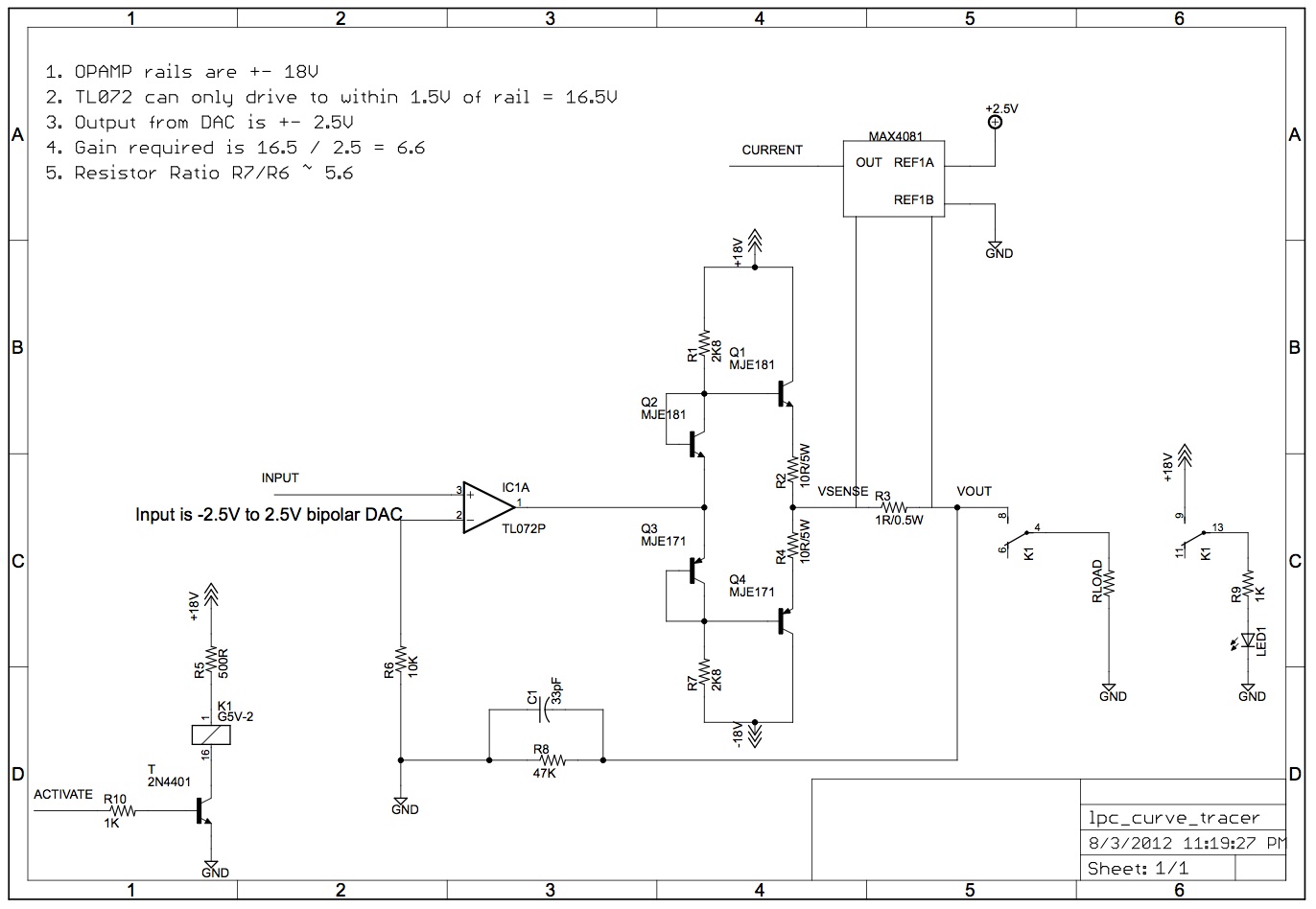
I've been toying with the idea of the following circuit:
I have a micro controller with 10 DAC outputs and 7 ADC inputs, that operate with bipolar supplies and can supply between -2.5V and 2.5V. I would like to use these to make a small program to characterize various discrete components like JFET's, BJT's, diodes, etc.
I was thinking that for small currents, I could use 3 DAC outputs as three virtual terminals to drive gate, source, and drain, or base, collector, emitter, and create test programs that either:
a) generated VGS verus IDS plots
b) find IDSS and VP for JFETS
c) find beta, VBEsat and VCE sat for NPN's and PNP's
However the main problems are:
a) that voltage range is not very useful
b) the DAC's poop out after about 2mA of source/sink current, which isn't very useful either
c) there's no way to measure current easily
So the circuit above attempts to address all three points. It is essentially a tried-and-true headphone power amplifier, with a current sense resistor buried in the feedback loop, and current is measured via a dedicated current sense amplifier. The circuit can supply approximately +- 14V and source/sink 250mA into a load, and assuming the output transistors are heatsinked properly, can even supply 500mA into a dead short.
I have added a microprocessor controlled relay so that the DUT can be disconnected while the DAC outputs are ramped to zero. Then the relays are closed and the curves/measurements are taken.
C1 reduces the gain of the system down to 1 at about 100kHz, which is about twice the sampling frequency of the DAC. I'm thinking that I should also add some capacitance to the output node, as slew rate is not important here: I want to essentially set up a DC bias condition, then take voltage/current measurements, then change the biases, repeat.
I'm also thinking about adding another ADC to sample the output voltage so I can perform offset trims digitally before the relays close (the DAC's are 12 bit, which means I have about 7mV of output accuracy).
Can anyone see any problems with this approach?
")