D-LA2A Support Thread

GroupDIY Audio Forum

Help Support GroupDIY Audio Forum:

This site may earn a commission from merchant affiliate links, including eBay, Amazon, and others.
I can only find measuring with the switch, not with the Potentiometer.
What is the maximum gain with the Potentiometer?

I don't know your DMM, but most DMMs are not that good with a 1K sine wave (they are build for 50 or 60Hz).
And, the LA2A output specs are 10dBm nominal with 16dBm maximum peaks.
The +21dBu measured with the DMM don't need to be the result of 60dB gain:

Zander said:
When I monitored the sound there was a point where it was louder before CW but measured lower.
 
[silent:arts] said:
I can only find measuring with the switch, not with the Potentiometer.
What is the maximum gain with the Potentiometer?

I don't know your DMM, but most DMMs are not that good with a 1K sine wave (they are build for 50 or 60Hz).
And, the LA2A output specs are 10dBm nominal with 16dBm maximum peaks.
The +21dBu measured with the DMM don't need to be the result of 60dB gain:

Zander said:
When I monitored the sound there was a point where it was louder before CW but measured lower.
The last (60dB) were with the pot. I have a fluke 187.  I think it's good for the task.
 
[silent:arts] said:
Sure, but since the 1st problem was exchanging a potentiometer with a rotary switch (and different gain range) we should look / compare for this first.
What about 1st channel original with a 100k potentiometer, 2nd channel with the switch?

One other mystery is the 21.61 dBU output which for sure wouldn't be any usable signal / waveform at all anymore.

Okay. I will measure everything again just to be sure. How did you measure your unit (27dB gain)? I just checked and the Fluke 187 has specified a .5 dB accuracy at worst up to 20kHz. But it's not recently calibrated I must add. I did not build the unit myself as I said. So I could go looking for a mistake made on both channels around the amps? Any voltages to check?
 
I am building a D-LA2A for a friend.  I am having an issue with channel 2.  I already pulled the PCB and checked all of the connections, verified that the relays are coming in, and compared voltages point to point with channel 1.

The gain knob on channel 2 does not seem to function properly(the pot is functioning correctly, and the wires are all in the proper spots in the connector) in that it does not kill the signal at zero.  Not being well versed in the theory behind this beast, as well as having a rather hectic work schedule, I figured that it would be wise to reach out to more experienced brains.  BTW, if I stereo link, the first channel drives the meters on the second channel.  Otherwise, the second channel does not seem to function correctly at all.

Any guidance would be appreciated.

Thanks,

John
 
Got two sets of matched pairs of photo cells, for a stereo unit. I'm a tiny bit confused about matching priority. 
There are two ways of doing this.
One: Using one matched pair in each T4B.
Two: Matching the GR cells of channel 1 and 2, and then the meter cells on channel 1 and 2.
I might've over thinked this a bit, but I don't feel that neither way gives me a functional stereo match as the two sets doesn't match (not quad matched)
 
You also have the stereo trimmer between the channels.
You want the matched sets to to be in the left / right, then use the stereo trimmer following the calibration procedure.

 
#1, otherwise the gain reduction is not correct on the meter for the calibration using the stereo trimmer.
 
Dear friends,
if someone has a layout of printed circuit boards for D-LA2A  to share or know a link where I  can download from the Internet.
Are there any where to buy the finished printed circuit board, or I  have to make a  printed circuit boards by my self.
Best regards
 
I am not sure about a layout available for the board but you can purchase the pcb's from Volker. Check out Silent:Arts in the white market.  He also sells the transformer.
 
febo2609 said:
Dear friends,
if someone has a layout of printed circuit boards for D-LA2A  to share or know a link where I  can download from the Internet.
Are there any where to buy the finished printed circuit board, or I  have to make a  printed circuit boards by my self.
Best regards

Hi, i have 2 D-la2a pcbs to sell, and one Power trafo for this project. If you are interested, just let me know. ^^
Hugo
 
Ok, newb question. Where is the power for the VU meter coming from? Where does the signal for the VU meter come from?

I am having a difficult time wiring the VU to a 2pos 6pol Alpha rotary and I can't seem to wrap my head around it.
There are a total of 4 poles on the VU and I am not 100% positive about what each sets of poles are for.

Does anyone have any insight as to how I would wire up the VU to a rotary style switch instead of a toggle switch?

__

Also, I am sure this has been asked before, but with the diagram for the Rondo transformer, is that ok for US 120V? Or will I have to wire something differently?
 
As to the VU meter connections I am going to assume you are using the Hairball meters in the BOM. I used the Hairball LED meters. The two poles located on the top of the meter are for powering the meters' light. I wired my VU meters up to the points where the 5 VDC relays are switched ON/OFF for each channel. This results in a meter lighting up when the channel is set to "IN" and turning off when the channel is set to "BYPASS". I think I used a 110 Ohm 1/4W dropping resistor at the meter. It is nice to have the visual indicator of the "IN/BYPASS" status. 

The rear facing poles on the meter are for audio and are wired to the center position of a DPDT ON/ON switch. This results in one switch position "OUTPUT" driving the meter and the other position for "GR" driving the meter. Basically, just use the wiring diagram and wire up the +/- to the rear facing poles on the VU meter. This requires a resistor at the VU (I seem to remember 3.6k). "OUTPUT" should result in the meter moving to the right for peaks. "GR" should result in the meter moving left. 

As to the rotary switch it is hard to offer specific advice without knowing the switch you are using. However, if it were me... I would just stick a couple short pieces of buss bar wire down into the molex connectors at the 5V relay header and then take wires with alligator clips out to the switch and experiment for a minute or two until I found the connections that yields the switch behavior I am looking for.

I moved the 5V voltage regulator off of the PCB and bolted it to the chassis for better cooling. It will need extra cooling if you are running the meters off the 5V header and have the chassis top in place. The regulator was fine on the bench with the top off, but closed up in the studio rack it was too much and the regulator was struggling. Seems fine now... (Remember to isolate the regulator from the chassis;)

If you are not using LED meters and are OK with the VU lights always being on when the unit is powered up just steal some power from the 6.3V heater headers to light the meters and the power indicator.
 
Noisy1 said:
If you are not using LED meters and are OK with the VU lights always being on when the unit is powered up just steal some power from the 6.3V heater headers to light the meters and the power indicator.

Noisy1 - THANK YOU. This is a huge help for me. I am indeed using the Hairball LED meter. The way I plan to wire this thing up is as retro as possible. I didn't plan on having a bypass, and would prefer if the meter was always illuminated.

Would it be best to steal power from the 5V or the  6.3v heater? I am only stuffing the right side, and have actually cut the left channel completely off. I have 2 heaters free. Do I need to purchase any resistors other than the 3k6?

I have some alligator clips, I can probably use them to figure the switch out - good thinking. That didn't occur to me.
 
Bypass the bypass (if you don't believe in it, ha)! If you plan to not use the bypass functions I would just place some buss wire jumpers in place of the relays.  This sort of thing is usually done with buss wire and teflon tubing to jumper on the underside of the board. You'll have to spend some time with the schematic and PCB to figure out a solution that respects the ground, positive and negative connections... or more alligator clips and a voltmeter to "buzz out" the connections.

I would use the 5VDC header to light an LED meter. If you bypass the bypass you will not have to wire the 5V supply header to the channel headers at all. You can then wire the 5V supply header directly to the meter LEDs and they will turn on/off with powering on/off the unit. Wiring to the 6.3VAC will cause the LED to flicker like a florescent light.  It is not exactly intolerable,  but I find it difficult to look at.

You need (must have) the 3.6K resistor for the audio hookup. The meter will not work correctly without it.

The current dropping resistor for the LED meter is something you can figure out using Ohms Law. I think the meter is 20ma and the header voltage is 5V. Play around a little bit with some values. I used a 110 Ohm 1/4W as it is what I had on the bench in front of me and I didn't have to get up and open up my parts bin. If I was buying something I would get a 1/2W as the price difference is negligible and the extra margin is a "make sense" choice. Had I bothered to get up I probably would have used something with a little more resistance as the meter light would be a bit more dim than it is.

Do you plan to have some sort of a power indicator light as well? You might want a resistor there to dim the light some. I used the old style red jewel light lens. Typically these would be a filament bulb and wired to the 6.3V headers. If you do this and do not use a resistor the bulb is quite bright. More Ohms Law or trial and error to find the resistance value that you want to provide the dim/bright level you like. 

Oh, just a fair warning on only wiring up one channel... I can totally appreciate the desire to be as retro as possible. I myself have a clear addiction in that direction. However, within 30 seconds of turning this on and hearing what it does you will want nothing more than for the second channel to work. This is a crazy good compressor.
 
Noisy1 said:
Bypass the bypass (if you don't believe in it, ha)! If you plan to not use the bypass functions I would just place some buss wire jumpers in place of the relays.  This sort of thing is usually done with buss wire and teflon tubing to jumper on the underside of the board. You'll have to spend some time with the schematic and PCB to figure out a solution that respects the ground, positive and negative connections... or more alligator clips and a voltmeter to "buzz out" the connections.

I would use the 5VDC header to light an LED meter. If you bypass the bypass you will not have to wire the 5V supply header to the channel headers at all. You can then wire the 5V supply header directly to the meter LEDs and they will turn on/off with powering on/off the unit. Wiring to the 6.3VAC will cause the LED to flicker like a florescent light.  It is not exactly intolerable,  but I find it difficult to look at.

You need (must have) the 3.6K resistor for the audio hookup. The meter will not work correctly without it.

The current dropping resistor for the LED meter is something you can figure out using Ohms Law. I think the meter is 20ma and the header voltage is 5V. Play around a little bit with some values. I used a 110 Ohm 1/4W as it is what I had on the bench in front of me and I didn't have to get up and open up my parts bin. If I was buying something I would get a 1/2W as the price difference is negligible and the extra margin is a "make sense" choice. Had I bothered to get up I probably would have used something with a little more resistance as the meter light would be a bit more dim than it is.

Do you plan to have some sort of a power indicator light as well? You might want a resistor there to dim the light some. I used the old style red jewel light lens. Typically these would be a filament bulb and wired to the 6.3V headers. If you do this and do not use a resistor the bulb is quite bright. More Ohms Law or trial and error to find the resistance value that you want to provide the dim/bright level you like. 

Oh, just a fair warning on only wiring up one channel... I can totally appreciate the desire to be as retro as possible. I myself have a clear addiction in that direction. However, within 30 seconds of turning this on and hearing what it does you will want nothing more than for the second channel to work. This is a crazy good compressor.

Would I be able to just wire the 5v to the relay and then split it to the VU? Taking the relays out at this point seems counterproductive as I've already soldered them in.

I'm not planning on having an indicator light, I can make do with the VU being the indicator.

I can't wait to hear this compressor!! This is one if the last pieces that will replace all my plugin compression.
 
I suppose you can wire up the relay so that it is always receiving power from the header and then also wire the meter. When the relay is unpowered the compressor is in "BYPASS" and you hear the input signal at the output. For example, if you pull the power plug out of the wall and run a signal through from input to output you will hear exactly what you put in at the output. Think straight wire from in to out. What this means is that you will need to wire up the relay to the 5V header and have the relay remain always powered "ON" (and unswitched) in order for the compressed signal to reach the output. It is kinda a goofy implementation, but if you don't want to take the relay out this is a work around to get the behavior you (sort of) want. It won't matter in this instance where you take the 5V from as the 5V is unswitched, or always "ON" when the unit is powered... just daisy chain it all up.

It is probably easier to just remove the relay and solder in jumpers than to mess with the god-forsaken molex pins to make header wires, but to each their own;) 
 
Don't remove the relays, without the proper tools chances to damage the PCB is high.
But don't power them always on if you don't want Bypass, it is a waste of power and only makes the regulator war.

Too way to solve the problem:

- jumper wires like Noisy1 suggested, but just do them on the solder side of the PCB under the relay

- look at the schematic.

signal flow for the input is
XLR to Input Molex -> Relay -> 4383 Molex -> Transformer -> 4383 Molex
change your wiring to
XLR -> Transformer -> 4383 Molex

signal flow for the output is
8940 Molex -> Transformer -> 8940 Molex -> Relay and VU Out Molex -> Output Molex to XLR
change to
8940 Molex -> Transformer -> XLR and VU

This way is nondestructive and reversible if you later want a Bypass
 
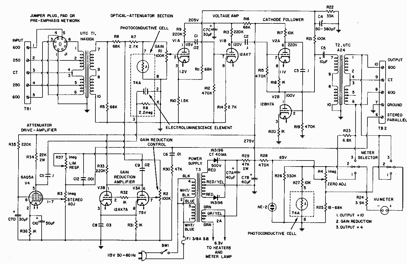
I just got back to figuring out what to do with this unit. I started to measure the nodes and found a schematic with voltages on it.
So far I have 101V where I should have 1.1 V this is between pin 8 of the 12bh7 and R18 referred to gnd. R18 is definitely marked as 1K (can't measure this in the circuit). Voltage drop across R18 is around 4.5V
Any ideas where to check?
Edit: See attached picture. 1.1V on the schematic should probably be 101V?
49646-281016082543.jpeg
 
Back
Top