dbx 166xl schemo...

GroupDIY Audio Forum

Help Support GroupDIY Audio Forum:

This site may earn a commission from merchant affiliate links, including eBay, Amazon, and others.
Hiya! The schematic you want is in the GroupDIY e-mail account.

Check out the meta-meta sticky post in The Lab section for details of the e-mail account. Once logged in, click on All Mail.

I've just checked and the schematic is on one of the e-mails about half way down on the first page.

Hope that helps!
 
Hi,

I am new here. I'm interested in the DBX 166 XL schematics too, but I cannot understand where I can find this link. Since the posts are from 2009 I think it might be dead too. Anybody knows something? Thanks
 
Hello, I'm interested in the DBX 166 XL schematics too. Could anybody post it please?
 
Thank you, but all posted schematics I already have and they are different from XL version. Not much different but I need to know right position numbers and values. Some parts such as resistors and capacitors inside my DBX are burnt.  :'(
 
Thank you for your reply. I borrowed a good one from a friend so I measured all components around signal input. Input filter resistors are 6k04, capacitors are 120pF, around diff. input opamp are 20k + 10pF.
Because I haven't NJM4560's (sooo poor opamp for my taste :p ) I upgraded to my favourite AD8512 and VCA to THAT2180. Now it is perfectly stable with wider and flatter amplitude response, lower THD+N measured ca. 0,008% at 1V, much higher CMR, manual balancing of 10p caps was needed - around 40dB on 5V/7ns edge square wave - for such simple circuit it's a good value IMO. I also downsized 47pF cap in VCA stage to 10p, it's better for this THAT.  I added 1k resistor to make limiter softer (don't like such hard limiting, really ugly for my ears) and 10p cap for better stability of output circuit. Let's look at attached scheme, I tried to make scheme from 166AD and 266XL versions, hope my reverse-engineered scheme fits real circuit and my changes are in red. Hope it helps someone to upgrade his DBX  ;)
 

Attachments

  • dbx_166xl_JeFmod_mkII.png
    dbx_166xl_JeFmod_mkII.png
    209.5 KB
Interesting. Thanks for posting. I have a couple of these in the closet that I never use. MIght have to play around with them now.

If you have any screenshots of tests/measurements you’ve made, i’d Be interested to see them.

Cheers,

BT
 
Hello Rackmonkey, yes I have some screenshots from oscilloscope of friend's original circuit and my modified for comparison (I allways do this). When I'll have some time I'll post them, please wait a while ;)
 
Nice trick with the soft limit. That stock limiter/clipper feature is absolute garbage, gonna have to try this.

By the way some time back I asked DBX tech support for a 166XL/166XS schematic - they are the exact same circuit - but never got a reply. It's very strange since the official DBX website has plenty of schematics of their other models: https://dbxpro.com/en-US/product_documents/en/schematic

I wanted to play with the timing circuits, especially the "auto" part. The manual timing part is the same as 266A (schematic available).
 
I finally got a reply from DBX support with the schematic. I'm not allowed to post it to technical docs section but if anyone needs it you can just email DBX support or fill their online support form and select "manual request" .

The schema is not particularly exiting compared to the 166A and 266A ones already available. They are pretty much the same thing. But nice to see correct part numbers and id's I suppose.

Oh and that "auto" timing setting... It's just hard wired resistance of some "good enough for everyone" values which you can just as well do with just the attack/release pots already.
 
OK, If you are not allowed to post it  :( , please only say - is my schema accurate? (except part no's)

Still thinking about soft limiter, it could be little more softer. We can add more diodes in series with existing ones (to add small voltage shift of it's treshold voltage) and one more diode with resistor in series and this combination add in parallel to two diodes in series. The area of transition to the limitation will be rounded by this. Theoretically we can add many stages like this to make limiter nicely soft :) And if I engage in a flight of fancy, it would be possible to make these resistors dynamically variable depending on the level of the signal using optocouplers with photoresistors... yeah, I'm gonna make my own comp-limiter 8)

But after listening test I can say - limiter with one resistor sounds much better than original. Maybe there are still too many higher harmonics, with circuit described above it could be little better.

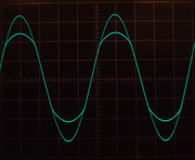
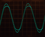
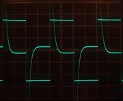
Some screenshots:
original dbx, with limiter activated at 20kHz
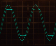

upgraded dbx, limiter dtto (note smaller delay of output caused by wider GBW of opamps)

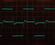
original dbx, common mode rejection for 10V square with 7ns edges; chA=2V/div chB=20mV/div

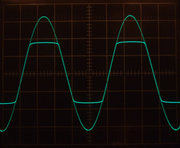
upgraded dbx, CMR dtto
 
jef111 said:
OK, If you are not allowed to post it  :( , please only say - is my schema accurate? (except part no's)
Yes of course it is. As you already noticed there's no difference to 166AD and 266XL in any meaningful way.

You can also get the full schema here: https://dbxpro.com/en-US/support (select 'Manual request' in the form and explain that you're really looking for the schema).
 
Thank you Kingston, I'll try it :)

Some another captures:
original limiter at 2kHz


upgraded


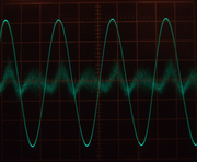
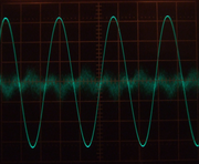
Harmonic distortion measurement on analyser BM534/HP334A with 80kHz lowpass filter:
original, chA=input signal 0,5V/div; chB=output of distortion analyser at 50mV/div; measures 0,02%; we can see a lot of noise and 2nd HD


upgraded, dtto, measures 0,008% (and it is nearly distortion of my generator)


Because the original circuit has a trimmer for VCA balancing, I rather used THAT2181 instead of 2180. It could be trimmed for slightly lower distortion so for the best performance I can recommend 2181 + manual trimming on analyser.
 
jef111 said:
Because the original circuit has a trimmer for VCA balancing, I rather used THAT2181 instead of 2180. It could be trimmed for slightly lower distortion so for the best performance I can recommend 2181 + manual trimming on analyser.

That's a good option. Another but expensive one is paralleling 2-4 that 2180's for lowered noise floor and absolutely perfect channel match. Note, in this case distortion depends entirely on which that 2180 class you choose (A, B or C)  Requires individual R9/R21 for each chip and compensated gain with R10 (looking at your mod schema). Same trick applies to the GSSL variants.
 
Yes, I know, but paralelling of VCA's is for another PCB it would be crazy here...
I have THAT2180A and THAT2181C. It's interesting that C grade could be trimmed to lower distortion than A grade on 2180 :)

I focused on noise of VCA a little more and found some noise modulation effect through CV pin. If RELEASE time pot is turned to minimum (or near it) I can clearly see some increased HF noise at output of distortion analyser. Normally I would not even notice it, I can see it only through analyser thanks to it's high gain. I thing it could be some HF stability problem around U6. When I tried to block pin1 of P8 by 100nF MKP cap to ground near it, noise disappeared. When I tried to add capacitor directly to pin10/U6 and to ground around U6 there was less noise suppression. I drew it in the diagram from 266xl, it seems to be relatively accurate, most of positions are the same.
 

Attachments

  • dbx166xl_sc_block.png
    dbx166xl_sc_block.png
    121 KB
Yes, I got it! :D
It was really a problem with HF stability, an 1ohm resistor in series with C29 helped. There must be a low impedance at HF on non-inverting input (without C29 opamp oscillates) but not zero so 1ohm seems to be a good value. I found the same problem with noise on friend's DBX and resistor helped too. Seems like an unsolved bug from factory. Now there isn't any change of VCA's output noise if I turning RELEASE pot.
 

Latest posts

Back
Top