DC 12V and 48V from single 12V transformer

GroupDIY Audio Forum

Help Support GroupDIY Audio Forum:

This site may earn a commission from merchant affiliate links, including eBay, Amazon, and others.

beatnik

Well-known member
Joined
Oct 18, 2009
Messages
1,271
Location
Italy
I am trying to come up with a power supply for a tube mic preamp using an off the shelf toroidal transformer.

This transformer has a spare winding 12,6V @ 1A and I want to power relays and LEDs with the unregulated DC voltage, a VU meter buffer with a 7812 regulator, and 48V for phantom power.

The first two are easy enough but I am wondering what would be the best way to obtain the 48V.

What about a voltage quadrupler circuit like the schematic attached plus a regulator with TL783 ?

On some tube preamps I have seen the 48V phantom derived from the HT rail and regulated with a zener diode, but I am wondering if it could be dangerous in case of a fault the HT voltage will reach the microphone.

Can you think of a better solution ?
 

Attachments

  • Full Wave Voltage Quadrupler.jpg
    Full Wave Voltage Quadrupler.jpg
    27 KB
Here's an image from the schematic for the dbx286s channel strip, which shows how they derive the 48vphantom power supply, using a voltage multilplier and a zener based regulator.
Source is 19VAC rather than the 12v you have available..... One extra multiplier stage maybe ? ....
 

Attachments

  • dbx.262.48v.jpg
    dbx.262.48v.jpg
    148.4 KB
Last edited:
Don't rely on dropping HT voltage - too dangerous. You simply can't trust your pass element to fail open.

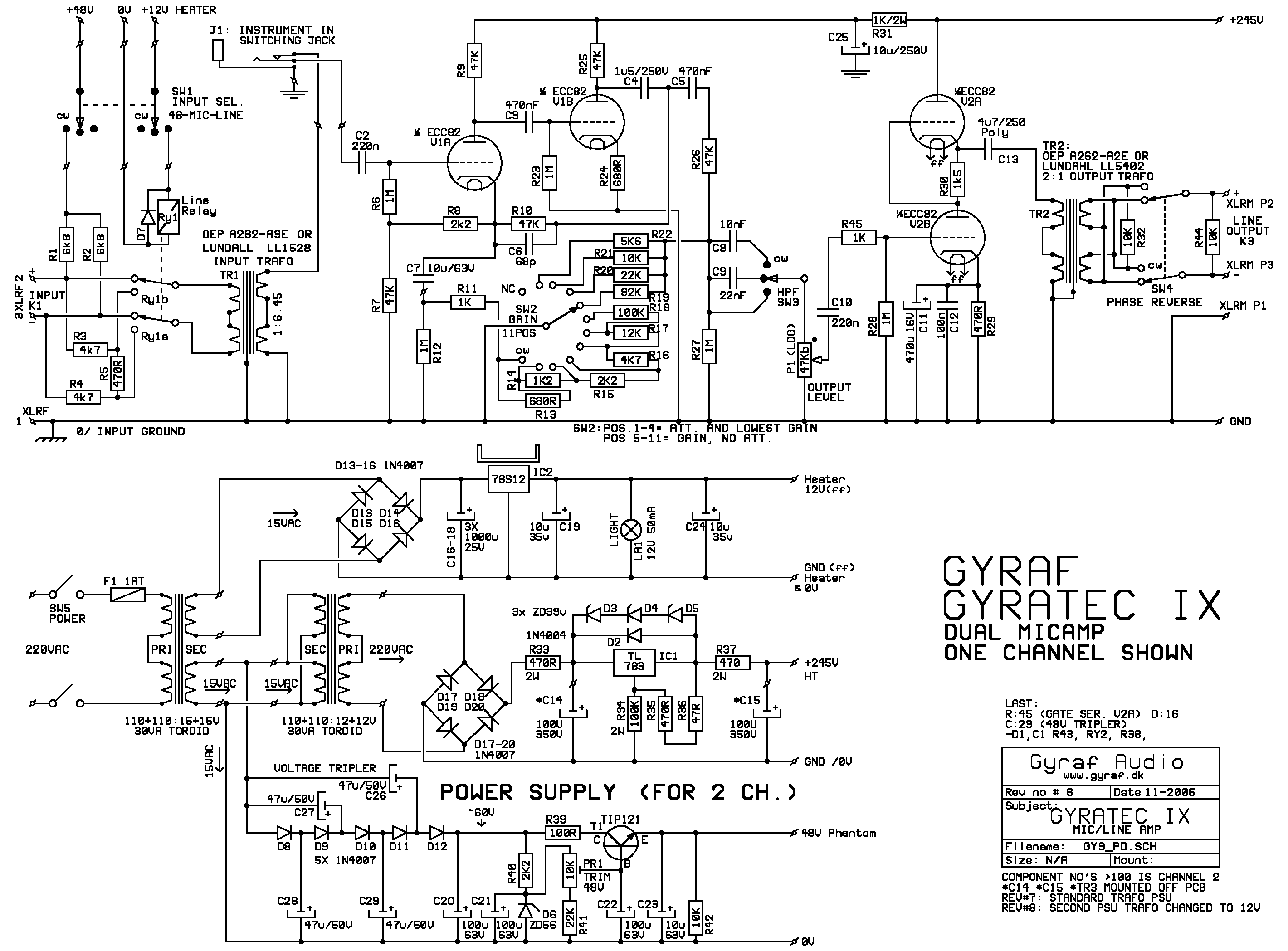
Look at e.g. the G9 project for 15V-to-P48 by a simple voltage tripler - you may perhaps need one extra tripler stage if running on 12V:


g9_sch.gif

http://gyraf.dk/gy_pd/g9/g9_sch.gif
 
I have been trying out this voltage quadrupler circuit, paired with the regulator copied from Gyraf G9 schematic

I can get a 48V output just fine, however the voltage present on the bridge rectifier B2 is a lot higher, I guess there is some interaction with the quadrupler ?

Is there a way I could obtain both 48V and 12V from a single 12V AC transformer ?

I would like the lower voltage rail to power relays, and perhaps a vu meter buffer.
 

Attachments

  • 48V + 12V.png
    48V + 12V.png
    27.7 KB
I have now butchered the PCB a bit to try out different things, but it was about 50V

This is with the 0V of 12V and 48V rail tied together

With the 48V 0V left floating voltage across C17 is about 44V
 
I have replicated the voltage tripler from Gyraf G9 and I can still get 48V after the regulator (the 12V AC winding output is rated at 1A so it produces 14.5V with no load)

The voltage across C17 is not constant but it's slowly rising from 20V to 24V and beyond.

I have to leave 0V reference from the 48V rail floating, because if connected to chassis it creates some short.

Do I really need a dedicated transformer winding ?
 
It really seems to me with this arrangement is not possible to connect a bridge rectifier to the same transformer winding as the voltage multiplier.
The 12V regulator section and the 48V regulator section work well on their own, but when powered from the same transformer winding this won't work properly, i think the diodes in the multiplier interact with the bridge rectifier creating undesired current paths.

I have tried a different approach, borrowing the circuit from the JLM AC/DC. See schematic below.
In this circuit the two rectifiers are isolated by C1 and C2 so they are not directly connected to the same transformer winding.
This circuit works well although the 48V rail goes maximum 36V, which is a bit strange because the schematic says you should be able to get 48V with a 15V AC winding, and my transformer outputs 14.5V AC

Would there be a way to modify the JLM circuit to increase the voltage going into the phantom power rail ?

Alternatively should I just forget about the 12V section entirely, and use 48V relays powered from the same rail as the phantom power, or would this potentially inject noises in the microphone line ?
 

Attachments

  • JLM ACDCv4 Schematic.pdf
    142.4 KB
Last edited:
I have tried a different approach, borrowing the circuit from the JLM AC/DC. See schematic below.
Schem is missing.

But why don't you just go back to your original circuit in post #4 and add coupling caps to your 12V bridge rectifier?
 
Do you mean something like this ?

I added the missing schem in the post above
 

Attachments

  • 48V + 12V rev.2.png
    48V + 12V rev.2.png
    37.8 KB
Back
Top