


Bo Deadly
Well-known member
Consider the following circuit (click to enlarge):
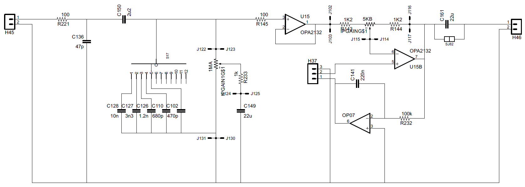
Normally I would just copy an existing design but I want to make a DI for guitar that has certain features (like being able to attenuate so that it can drive a Fuzz and not just get massive blocking distortion).
The immediate concern I have is the noise gain of the active volume control. It's range is +-14dB but the noise gain is +16db and -1.5dB. So in the attenuated position, the noise gain would be 13dB more than a simple non-active control + buffer. Right?
So how is this sort of thing done normally? Is there a particular circuit that I should look at?
Criticism about other parts of the circuit are welcome. The switch with caps and 1M pot on the input are just supposed to setup the input impedance environment. This will ultimately connect to a relay switching network to other boards which could be anything. So the optional servo or coupling cap ensures zero offset.


![Soldering Iron Kit, 120W LED Digital Advanced Solder Iron Soldering Gun kit, 110V Welding Tools, Smart Temperature Control [356℉-932℉], Extra 5pcs Tips, Auto Sleep, Temp Calibration, Orange](https://m.media-amazon.com/images/I/51sFKu9SdeL._SL500_.jpg)


")