Discrete Mixer (reuploded fotos)

GroupDIY Audio Forum

Help Support GroupDIY Audio Forum:

This site may earn a commission from merchant affiliate links, including eBay, Amazon, and others.
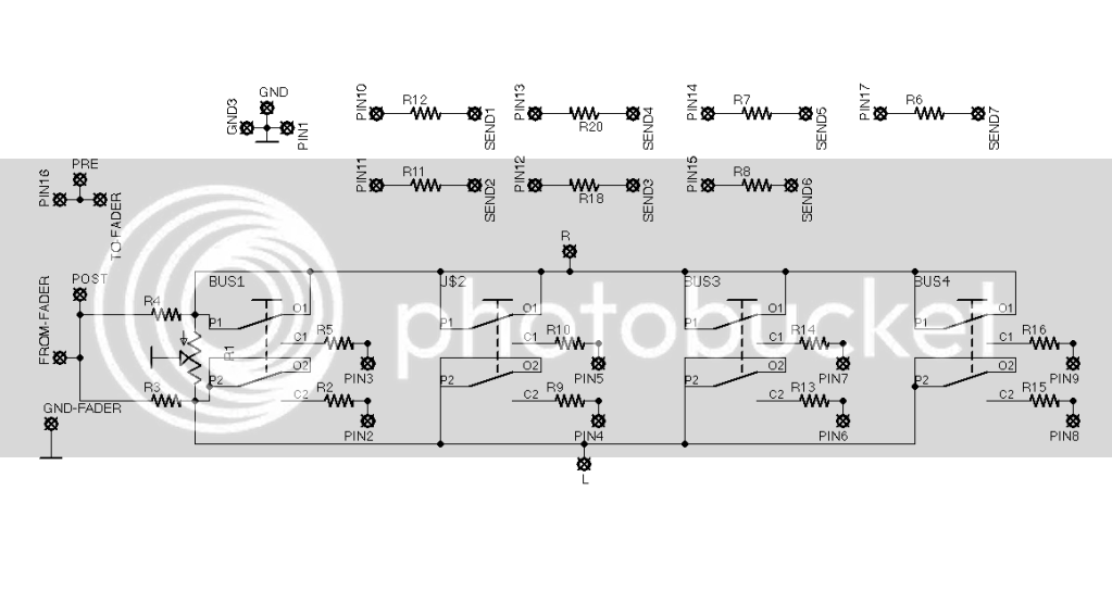
Send/Pan Schem
PanSend.png


The pin# are I/O slot to a  buss board. Send# is the retern from pin 2 of same send pot may be mono or stereo, using master pan or independent one)


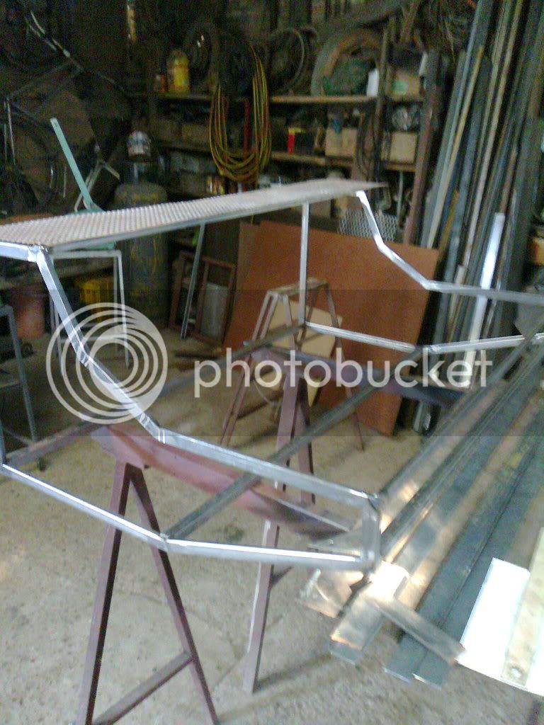
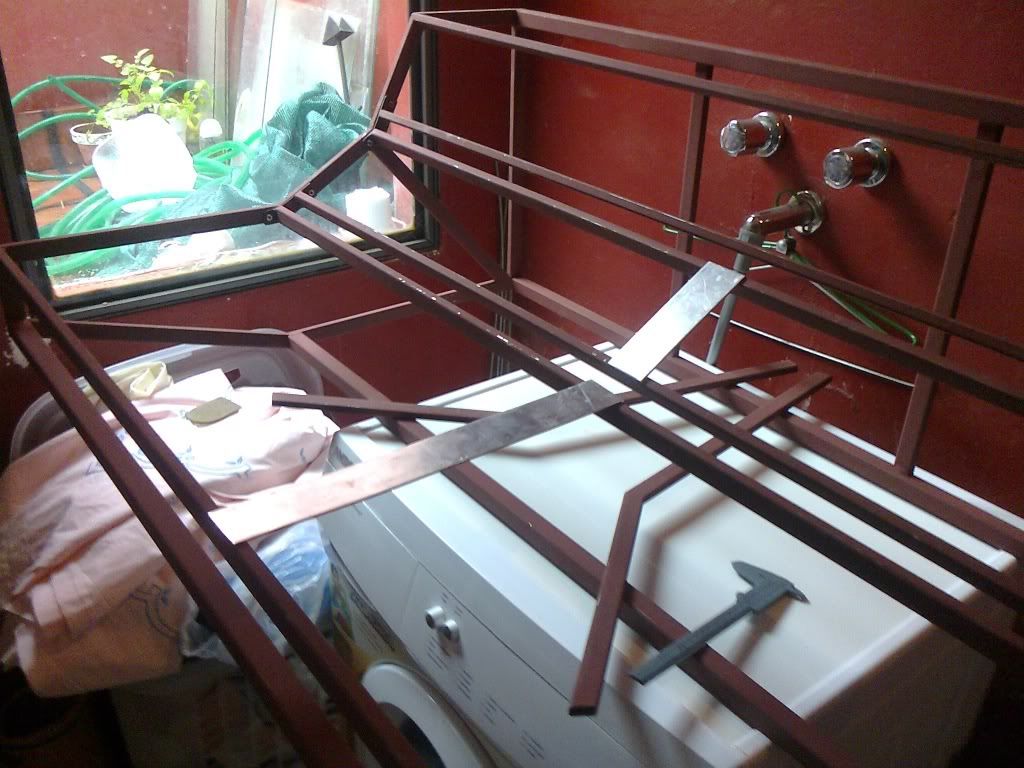
Here are some pictures I take today, just with the phone, sorry the quality. It's taking shape...
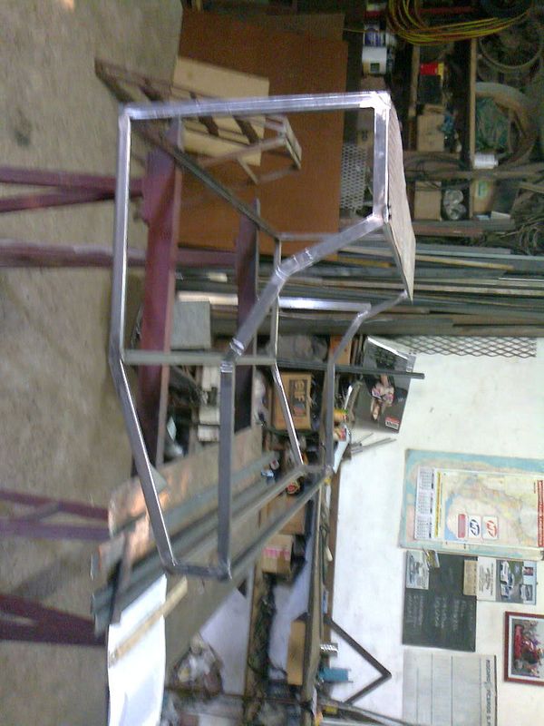
Foto0028.jpg

Foto0027.jpg


Side and little front pannels going to be wood, with conductive foil inside for faraday sheilding... thinking about the legs, maybe the same wood for the sides could be legs... what do you think? would be great any opinion here.
 
Hey, some news around...

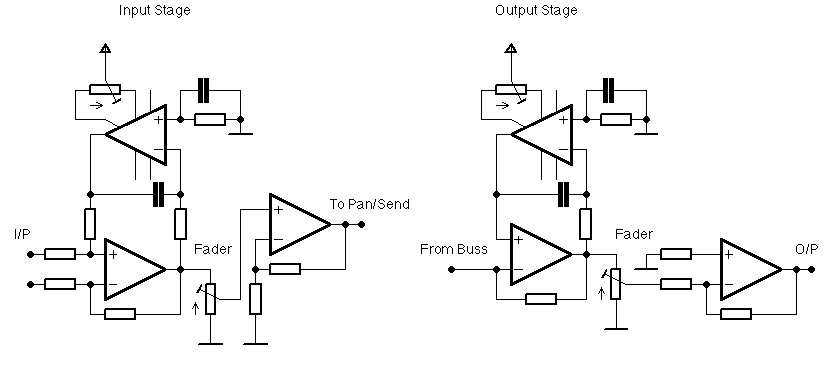
today just fix the issue of servo, working great now. want to ask another opinion... in order to take out the DC from the faders was thinking in adding at the input amp a servo too but still could have DC at the output buffer (a 3rd servo?)
SimplifiedSchematicV2b.png


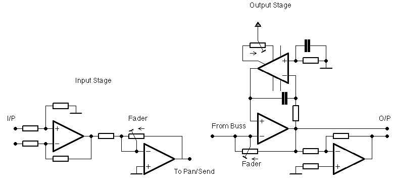
or should i use active faders? thinking that too because couldnt find good faders around. The simplified schematic of this topology would be something like this... what do you think? with active faders i can avoid the output buffer, but should have to add an inverting amplifier to busses to correct the phase, with it i could also use electronically balanced output
SimplifiedSchematicV2a.png


I think the second topology is simlper and avoid signal through (bad) faders.

Waiting your opinion

JS
 
hey man, nice project, thanks for sharing the info! One day I'll get something like this done!

As for the fader schems, the first makes more sense to me, but take that with a grain of salt!! Do you need the feedback resistors in the buffer after the fader in the input stage?  Also, instead of servos, wouldn't output caps work fine and be simpler? 

Did you solve your trafo parts issues? I live in brazil, maybe I can help. We have nice G.O. laminations here.  Let me know if you want I can maybe send you some. I've used them for API type output trafos they are very nice.
 
the feedback resistors are for a little boost for 0dB fader position not be the top... here in argentina cant find good caps or faders, the alps are too expensive (around 20 U$ each) so, for 16 channels and 8 buses (no fader to sends) have 500U$... plus, i dont want faders, I prefere rotary pots, to mix hearing and not looking... maybe faders at buses, but dont know... I couldnt find plastic pots, so i prefer the signal doesnt pass throgh pots or caps... that's why the servos and the second schem... i know it isn't an usual topology, but i belive it could work...

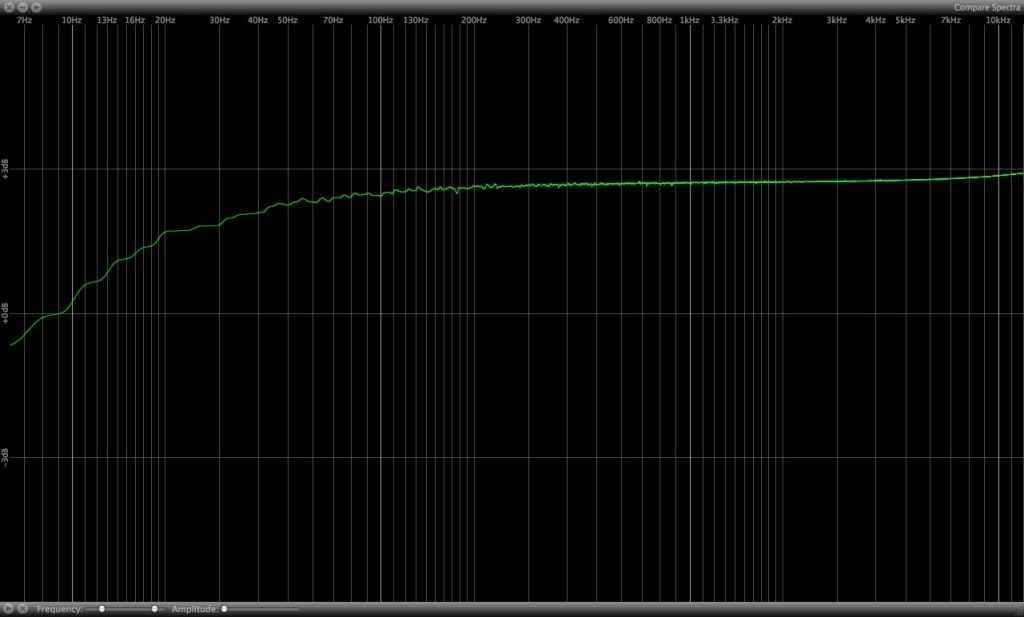
For the trafos I find a GO laminations that are working find... have to try thiner wire and/or bigger core, but for now i can get -1dB at 30Hz, really good compared with -3dB at 100Hz i get with the common lamination... I made it with trifilar (3 simple wires) winded together of .03mm, each layer insulated with film, 280 turns each winding. When I have the final version I upload the photos and all experience in a new topic.
Here is the respone
respuestatrafoGO.jpg


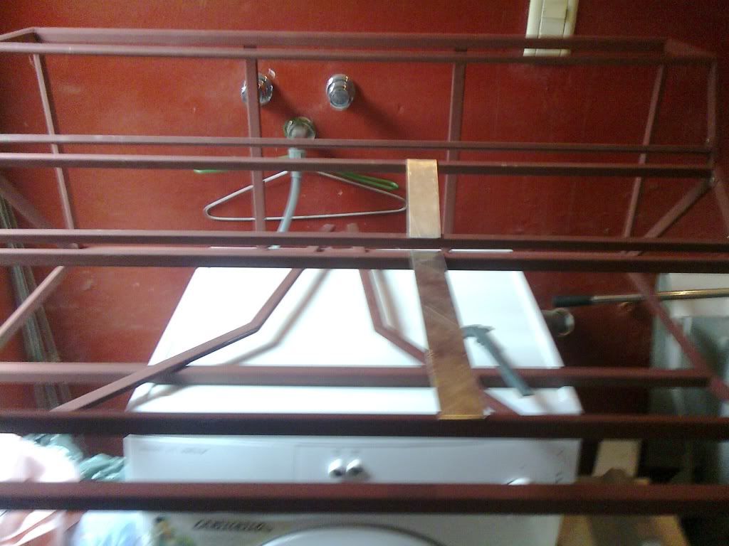
I have the chasis at home... Here are some pics
Foto0032.jpg

Foto0031.jpg


JS
 
Nice progress shots. 

I see what you mean on the resistors now.  As for faders/pots, try Omeg in the UK.  The pots in your pictures look like the ones they sell locally here, which are pretty crappy.  Omeg's are conductive plastic, they are cheap and they'll do all kinds of custom stuff. Or get some from Mouser/digikey.  Tax and all, it's still better than the local stuff. Try to get something sort of sealed if you don't want them noisy with use.  Caps you can get from TAW in the US, in the quantities you'll need they'll make you a good price.  Then you can simplify your life and remove the servos. :)

If you have GO lams then you're fine. The wire size and turns is from the API 2503 trafo?  That is quadfilar, on 5/8 x 5/8" EI, so if you are using that core size and winding trifilar you should have plenty of room left for more wire if you wish, or thicker wire. Unless your wind is uneven which could negate the benefits of multifilar winding.  Anyway neither thinner nor more wire should be necessary unless your use is totally different.  API has been using 280 turns of 29AWG for decades and people don't seem to be complaining. ;D    The response chart may also be better in actual use, if you're driving this with a signal generator and it's impedance is higher than the output of the opamp that would normally drive the transformer.

anyway, good luck, very cool project.
 
Nice project.

joaquins said:
that's why the servos and the second schem... i know it isn't an usual topology, but i belive it could work...

I've used an active level control myself although not in a mixer.  I don't see why it wouldn't work well (there's a noise advantage of course in that gain is only added if it's needed) but, as I'm sure you know, the input impedance can get low at the highest level.  As long as your driving amp can handle it then I think it's fine. 
 
Jean, the impedance shouldn change, the fader buffer is virtual ground, so the potential at the inverting input should be zero then the Z seen by the driving should always be the interstage resistor. I'm wrong?

Mitsos, i think i wind it nice... few wire crossed and i made it layer by layer insulating the layers with kitchen film (dont know the insulating propertys, but at least doesent take space). The DC resistence, capacitance and inductance match really well between windings. Although the core size and wire are really close, but it fits tight. The response are with the output amp, but the one designed for transformerless so it have decoupling resistors. I can get down the output impedance about 66Ω. Im realizing this now i tell you, have to try without them and should get really better, maybe thats why just have less than 3dB gain when should be around 6dB. maybe I should put a couple of chokes (4.7µH) in parallel with resistors, something like jensens oli.

I know about UK and US providers, the matter isnt the shipping nor pricing. The costumers here in Argentina are really hard, they doesent let anything to get in the country, so if i buy them or ask you to send me the laminations they will keep them and i'll never see anything, that's why i have to deal with the stuffs i can find here. the servo isn't a problem, it's really simple and i love the idea, also like jean said, there is a noise advantage with active faders. I wish could have nice pots and faders, not just for the mixer, but for the whole project, but now i cant... wish next year the costumers be better and i could get all that pretty stuffs.

Thanks for the help and intrest, when i have it finished and solved i'll organize all docs and upload them. Cheers.

JS
 
joaquins said:
Jean, the impedance shouldn change, the fader buffer is virtual ground, so the potential at the inverting input should be zero then the Z seen by the driving should always be the interstage resistor. I'm wrong?

I looked at the circuit 2 picture on the right which doesn't show a resistor.
I was also thinking more of the Baxandall active volume control.
 
Hey man,

not implying you wound it badly, it's just really difficult to handwind multifilar or wind with a manual feed machine.  The fact that you wound 3 wires with the same amount of turns as API (and others) wind 4 wires and are running out of room shows that the wires are either not even or not tight enough, or a little of both? But maybe removing the resistors would solve that.  Try one of your 2520s driving the trafo through a 470uF cap. No resistors, and see what you get.  I've never used an OLI, it's supposed to reduce the effect of capacitance from really looooong cables. 

Customs suck.. Here it's the same. I *almost* always get the packages but they take 30-45 days sometimes (I'm waiting for 2 silent CPU fans right now, it's been 40 days...).  All in the name of protecting local industry.  So much for progress.  ::)

Good luck with the project, thanks again for sharing the circuit blocks and photos.
 
Jean, this circuit is the summing amp, the resistors are in the pan/send board wich is shown before... we weren't understanding, I know the baxandall issue, but i use the pot just in feedback, dont know if the feeling of the fader will be find, have to try it.

Mitsos, i said that for you to know that i didn't wind it messy, I use 3 single wires, i put 3 wire reels, and wind them as tight as i could, maybe not enough.
The OLI i said because the capacitance between the windings is really high and OLI would stabilize the opamp, i can get a resistor and a choke of 4,7mH for cents.. and instead of the cap i use the servo so it wouldnt have dc across the primary. Ill try taking out the resistors and putting a cap for now, then I show the response, but up to thursday I wont be able to do it...
 
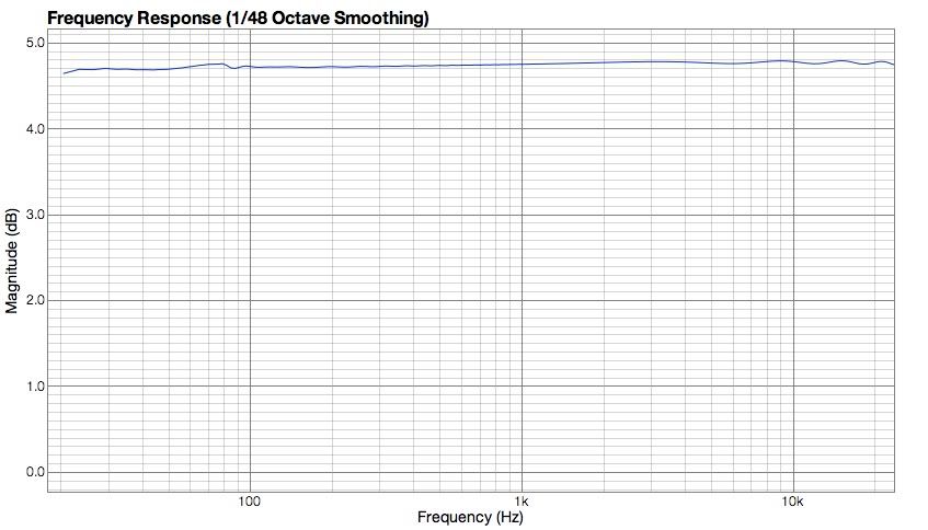
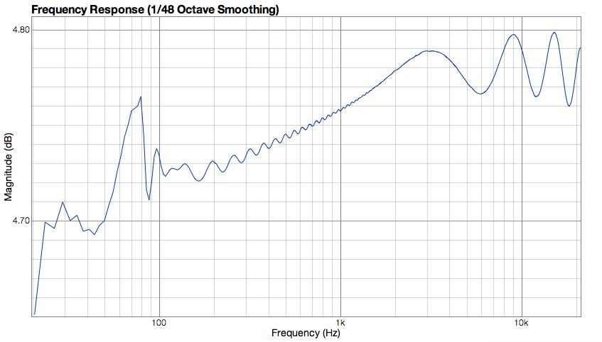
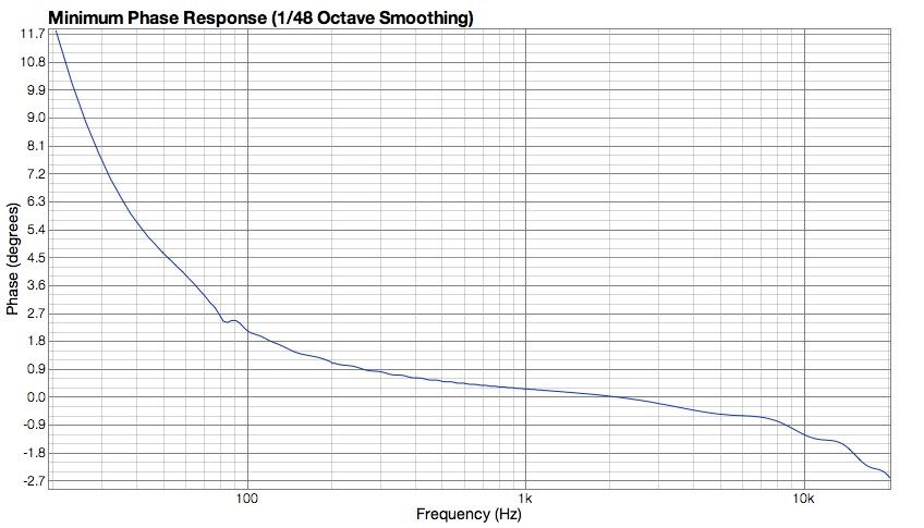
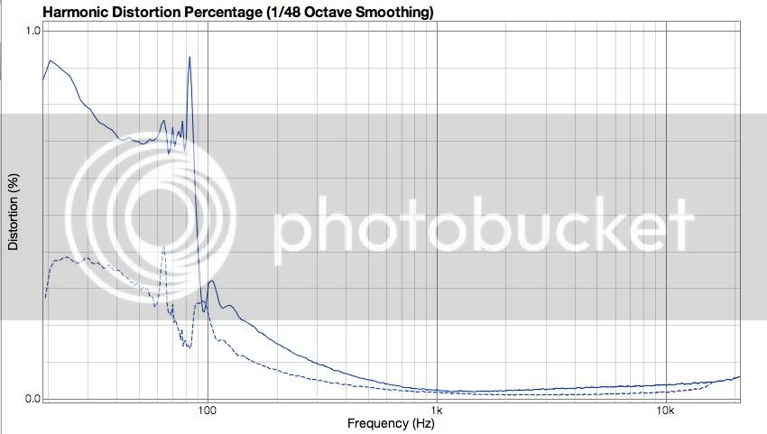
Here again... new output transformer response, change the 33Ω resistor for a 220µf cap, don't have 470µ at home... I don't have the servo output finished yet.

freq.jpg


freqzoom.jpg


phase.jpg


THD.jpg


(Solid is 2nd harmonic, dashed is 3rd)

JS
 
I already have the new boards working ok, when i have the measurements I upload the boards and values... Cheers

JS
 
I need some help here, in the first stage i can't read any DC voltage (thanks to DC servo) but I have a DC of 1,6V aprox in the out of the second stage, I use 2 1K res to ground in parallel to have the same DC resistance in both inputs...

I measure a DC offset of around -0.3mV of the op amp I'm using... (can't be so exact beacous of the multimeter but cant be more than 1mV)

when I start up the device it's output is lower (couple of mV) but suddenly rise up to 1,6V or so... any ideas??

could it be because i didn't put a cap in de feedback? just thinking, but it should have oscilations in HF but no DC offset I think... It does sound well, but have that offset. Will try it, but any ideas acepted in the mid time, maybe I'm forgetting something else.

Thanks

JS
 

Attachments

  • sumamp.gif
    sumamp.gif
    14.2 KB
Hello!

1,6VDC is alot!!

One idea is to replace the 1k resistors from the non-inverting input to ground with a potentiometer and see if you can cancel out the offset.

I also suggest to to have a closer look to the input- and output-signal with a scope. This will tell you  more than a DMM.

all the best,
Wolfgang
 
Hey, I put a 100pf cap across the feedback resistor and the DC is no longer here... seems that it was a oscilation, seems to be that my opamps are no so stable at unity :S. Now I have 0.5mV and the circuit has been working one hour.

thanks wolfgang for the help, it was the next step in the try, but no need... I don't have a scope... generally use the computer but it just go up to 96khz (192khz sampling rate)

Well, now is time to start building all the boards, first I want to try a stereo chain, but only have one transformer by now, so transformerless for now. Tell you when I have some news. NowI'm working on a 990, I just did the board, now I have to solder the parts and see what happens.

JS
 
Thanks, some kind stopped because a lot of reasons and I wish to be working on it... but it will keep growing at some point.

I've started a topic in drawing board to discuss some details about it's design but no much feedback since. Here is the link.
http://groupdiy.com/index.php?topic=50205.0

JS
 
nielsk said:
Don't you need the buss assign switches to ground the mix resistors when they are not selected to be fed from the source?

There are two things to look to decide this.. one is DC offset (better if resistors are always connected because same z always) and noise (better if resistor open if unused because noise gain goes down)

I went for noise because I'm using servo to deal with DC. With passive sum or so called the gain of each input may vary, with virtual earth it doesn't.

JS
 

Latest posts

Back
Top