Hi... I've started a topic in the mixer part but I think it would be better here...
Here is the old topic. http://www.groupdiy.com/index.php?topic=48042.0
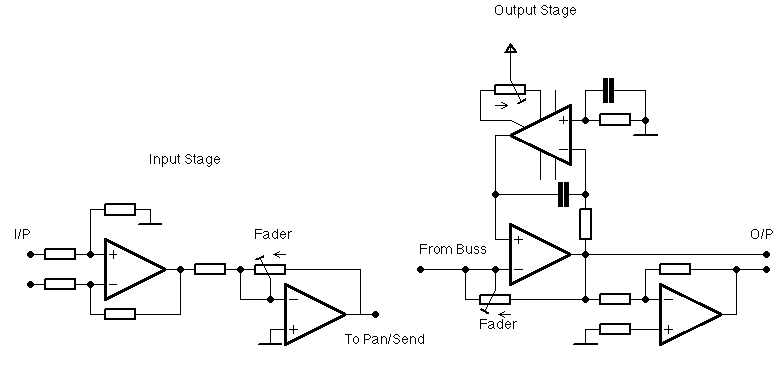
I'm building a mixer with 2 500/51X slots for each chanel, the initial project is 12 channels and 2 sub-master (anyone could work like master)
Later I will add 4 channels for working with stereo FX and so, (I've started with 12 because is the number of outputs I have from the computer) and 2 more sub masters.
Here is my question of the day: How should I interconnect all modules? I'm using pinheads for all the mixer part: buses, input, fader, summing amp and output amp. I mean... Should I use ribbon cable or a board to plug all them in? I'd made a board for buses but I won't die if I don't use it...
In any case, I was thinking about using a heavy solid wire for ground going down each channel and then taking all together, like a comb, how should I connect my pin connector to the heavy clean ground? Any suggestions?
here some pics, more on the old topic and even more comming later (I have nothing intresting now for new pictures)
Pan & Assign
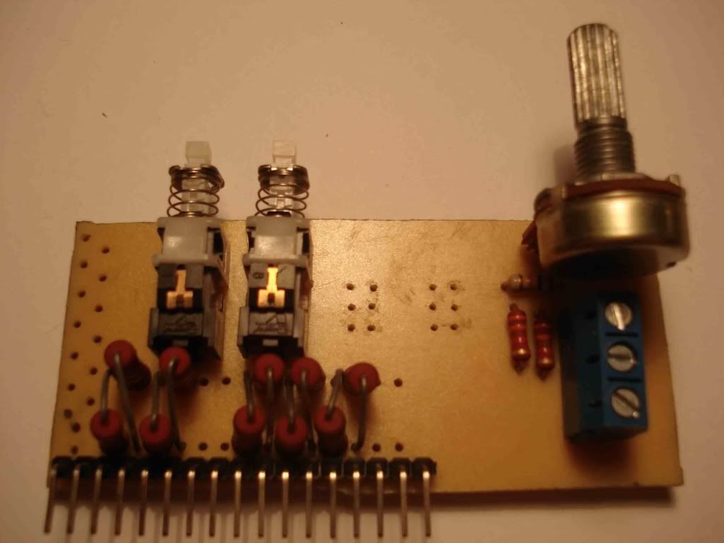
In the board
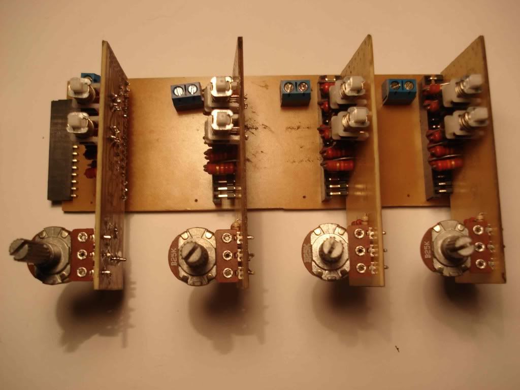
Input/fader (left) and Summing/output amp (right) with and without opamps. (sorry crappy photos, just the cellphone here... Hey, my little feet wanted to show in the pic!)
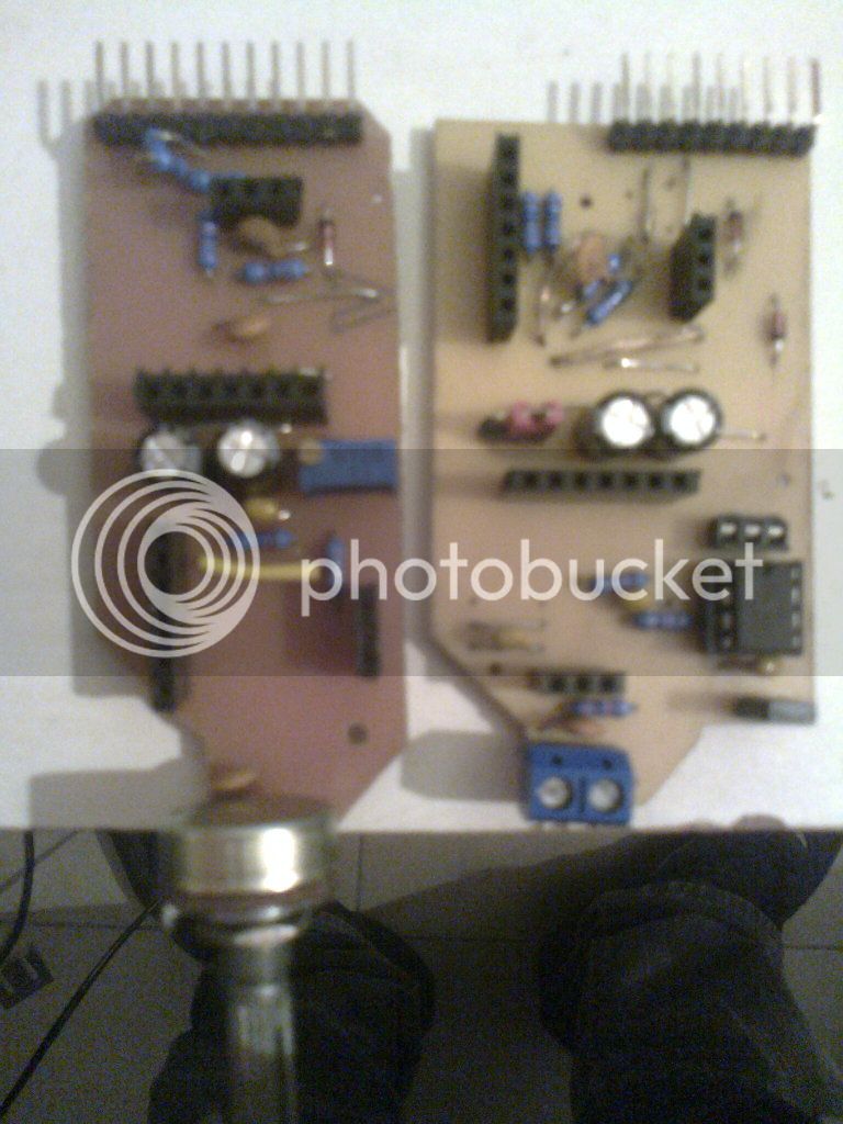
They are not the totaly final boards, just add a little mods (servo to the fader and insert points to use the input amps and then send to the slots) But are very close. Wating for comments...
JS
Here is the old topic. http://www.groupdiy.com/index.php?topic=48042.0
I'm building a mixer with 2 500/51X slots for each chanel, the initial project is 12 channels and 2 sub-master (anyone could work like master)
Later I will add 4 channels for working with stereo FX and so, (I've started with 12 because is the number of outputs I have from the computer) and 2 more sub masters.
Here is my question of the day: How should I interconnect all modules? I'm using pinheads for all the mixer part: buses, input, fader, summing amp and output amp. I mean... Should I use ribbon cable or a board to plug all them in? I'd made a board for buses but I won't die if I don't use it...
In any case, I was thinking about using a heavy solid wire for ground going down each channel and then taking all together, like a comb, how should I connect my pin connector to the heavy clean ground? Any suggestions?
here some pics, more on the old topic and even more comming later (I have nothing intresting now for new pictures)
Pan & Assign
In the board
Input/fader (left) and Summing/output amp (right) with and without opamps. (sorry crappy photos, just the cellphone here... Hey, my little feet wanted to show in the pic!)
They are not the totaly final boards, just add a little mods (servo to the fader and insert points to use the input amps and then send to the slots) But are very close. Wating for comments...
JS