Discrete Voltage Regulator

GroupDIY Audio Forum

Help Support GroupDIY Audio Forum:

This site may earn a commission from merchant affiliate links, including eBay, Amazon, and others.

Samuel Groner

Well-known member
Joined
Aug 19, 2004
Messages
2,940
Location
Zürich, Switzerland
Hi

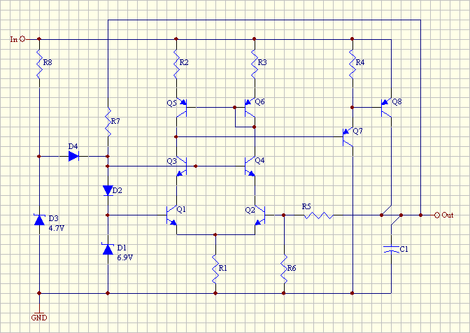
Consider the following conceptual schematic for a discrete low-dropout voltage regulator:
discrete_voltage_regulator.gif


Let me ask a few question before I attempt to build a realisation:
* Is the startup network R8/D3/D4 sufficient to guarantee startup?
* Q8 will need a reverse-protection diode; is there a need for a similar protection scheme (anti-parallel diodes as we know it from opamps) for Q1/Q2?
* Simulation indicates that the output impedance considerably peaks at somewhere above 100 kHz if C1 is chosen at 1000 uF. Increasing the capacity by one to two orders of magnitude solves this but it ain't practical. Is there another simple technique to address this issue?

Thanks for your help!

Samuel
 
You might want to consider a diode in series with r7 so it doesn't suck current out of bias string at startup.

LDOs can have stability issues, that output C is also causing phase lag in negative feedback path. I don't see any internal open loop gain compensation pole.

JR
 
I'd recommend that you have a reasonable value for ESR in the C1 model before worrying too much about the apparent line and load regulation versus frequency.

I'd also put an R in the collector of Q7 to protect it during fault conditions.
 
Thanks, indeed ESR is an important factor. Any ideas about the need for protecting Q1/Q2? I see that you didn't use protection in the regulators you published in your AES preprint.

Samuel
 
I think probably the thinking there (1997) was that the circuits would be safely embedded in the unit and not liable to abuse. But I may have just missed something---I didn't do much sim in those days. Now I routinely check reverse-bias transients on power-up and power-down in sim, as well as short-circuit fault conditions.

It's perhaps interesting that this regulator proposed gives my Spice engine conniption fits based on the choice of ESR. Initialization is the problem, evidently. I gave up on it for the moment after trying a number of tricks which usually work.

The other dismal property of the Spice simulator I have is a really lousy zener model, which resembles reality in a couple of ways and is wildly wrong in others. Someday...
 
Adding one more resistor from base of Q110 to regulated output could provide a fold back component to the current limiting.

I still remain a little apprehensive about stability, and C103 is not helping, but I've already registered my suspicions in that regard.

JR
 
[quote author="Samuel Groner"]So here's what I've come up with: discrete_series_voltage_regulator_r1.pdf

Does that make sense?

Samuel[/quote]

Looks like it might work reasonably well. One minor concern is blowing out one of the 914B's (D106) by exceeding the peak current under a hard output short circuit, via the two 'lytics. I think 914s are actually pretty hard to destroy, but someone recently critiqued a design where I had no series limiting resistor when charging a 22uF electrolytic. I decided it was easier to add one than argue, let alone be wrong.
 
Adding one more resistor from base of Q110 to regulated output could provide a fold back component to the current limiting.
I've considered that but I'm somewhat concerned about startup behaviour, and fold-back ain't gone improve this. So for a first revison I think I let the protection as it is; perhaps adding a thermal shut-down is in order though.

One minor concern is blowing out one of the 914Bs.
So do you think it would make sense to replace the anti-parallel diodes with single base-emitter clamps for Q101/Q102?

LTP transistors practically work in the saturation region.
Vce is about 0.6 V, so we're fare above saturation (spec'd at 0.25 V maximum and 0.075 V typical). Operating LTPs at 0 V Vcb is standard practice in IC opamps and definitely not a problem.

Samuel
 
[quote author="Samuel Groner"]
One minor concern is blowing out one of the 914Bs.
So do you think it would make sense to replace the anti-parallel diodes with single base-emitter clamps for Q101/Q102?
Samuel[/quote]

That would shift the burden of excessive forward current to the left-hand LTP transistor's B-E junction. Maybe just some strategic small series R? You could still get most of the benefit of the noise reduction of bypassing the feedback R if there were a small R in series with the cap.
 
Maybe just one on the right, and compensate if desired with the value of the series R to the C on the left. This, that is, for the original cross-clamping arrangement.

It doesn't take much---I recall I used 51 ohms in the example I mentioned. The surge voltage involved there was about 20V, although the capacitance was smaller. Manufacturers' datasheets for the diode should be consulted.
 
Hi,

I have no knowledge about the design, but would like to know what advantage about the discrete regulator over the IC like LM317?

Thanks
 
The (potential) advantages of discrete design which matter for me are as follows:
* The output noise of the regulator can be very low. Around 10x to 100x lower than typical ICs.
* Ripple rejection (the insensitivity to input voltage variations) can be better than for typical ICs. IIRC simulation indicated at least a 20 dB improvement over typical IC specs.
* Output impedance (the sensitivity to output current variations) can be lower--haven't looked in detail at this in comparison to ICs so won't comment further on this.

There is no magic involved though; these advantages come mainly from the fact that I've used several large electrolytics to filter reference noise and to shape the feedback loop (in some ICs you can at least partially emulate this by providing external capacitors but usually it doesn't work as well as here), allowed a large quiescent current and because discrete design has access to good quality PNP power transistors.

Samuel
 
[quote author="laiben"]but would like to know what advantage about the discrete regulator over the IC like LM317?
[/quote]
Note that the reasons as given by Samuel compare (t)his nice discrete design with typical ICs out there, which does not necessarily mean that ICs can't be better than 'those types'.

The three given points won't represent fundamental limitations for ICs (nor do they claim so :wink: ), but of course then I'm not talking about getting all caps inside - that obviously becomes impractical pretty soon...


Apart from that (and as without doubt already known), how about adding some more discrete ?

http://www.wenzel.com/documents/finesse.html

cleanup1.gif


etc

Regards,

Peter
 
I'm not aware of an IC regulator which would come close to the expected performance of the discrete design; in fact my range of one to two orders of magnitude improvement already includes the higher performance parts (with the LM317 being closer to the two orders). This is particularly true if you consider that my suggested design is a low-dropout one.

Another question is of course how good a regulator you really need, but this can't be answered without context.

Samuel
 
[quote author="Samuel Groner"]I'm not aware of an IC regulator which would come close to the expected performance of the discrete design; in fact my range of one to two orders of magnitude improvement already includes the higher performance parts (with the LM317 being closer to the two orders). This is particularly true if you consider that my suggested design is a low-dropout one.[/quote]
My point of departure was that despite integrated regulators with at least comparable operformance to the discrete design might not be on the shelf already, it didn't seem because of fundamental limitations of integrated circuits*. You didn't claim that either, but a casual reader might have read that from your answer, and that wouldn't be justified, also since you didn't even say so.

Another question is of course how good a regulator you really need, but this can't be answered without context.
Fully agreed.
For fun I might add that clean-up shunt to something for instance, but will it really be needed ? But that's often the case here on these pages'n'threads of course: despite we might have a feeling sometimes that's ranging from 'perhaps-not-really-needed' to 'deliberate overkill', who cares ? 'For fun', 'because I wanted to' are perfect reasons, at least for DIY. For economical design it'd be another discussion.

Regards,

Peter


*: So while not there, that doesn't mean they couldn't be made - reasons for not being able so are not apparent to me (distinction between fundamental vs practical limitations, my point being about the former).
 
From what I understand, the reasons as to why a discrete Vreg may offer advantages in certain scenarios would be similar to why a discrete circuit can offer an advantage in the case of say, a mic preamp. Modern epitaxial transistors are not only fantastically quiet, but can operate at higher voltages than your average mass-produced IC. This enables the designer to tailor the circuit to be optimised for the application in hand.

Having said that, if I'm using an op-amp, be it discrete or monolithic, running in Class A, pulling 25mA per rail at 24v - and I can get 130 usable dB when using the venerable LM317, what advantage will a discrete Vreg give me?

If we take a modern design of op-amp, offering over 100 dB of PSRR, what advantage will the discrete Vreg design offer me?


Cheers,
Justin
 

Latest posts

Back
Top