Distribution Amp with level and balanced outputs

GroupDIY Audio Forum

Help Support GroupDIY Audio Forum:

This site may earn a commission from merchant affiliate links, including eBay, Amazon, and others.

conleycd

Well-known member
Joined
Aug 9, 2007
Messages
213
Okay...

If people could take a look at this I would be greatly appreciative (as always).

Here's a stab at a component that I need for my "hard to explain" summing/parallel mixing/flavor box...

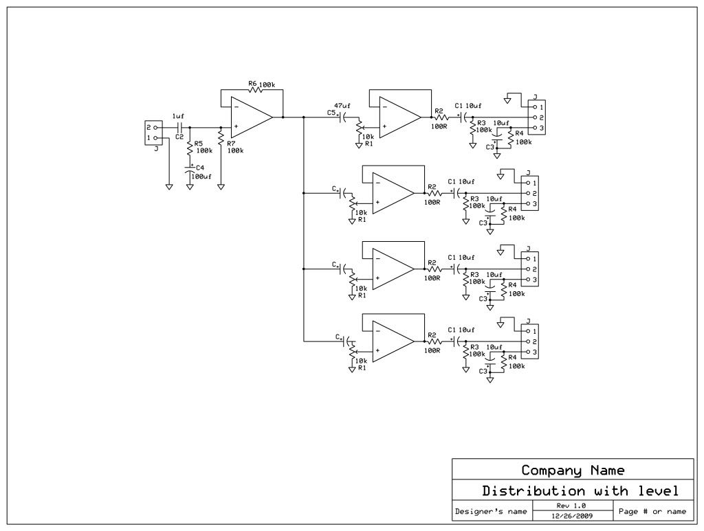
This schematic is supposed to take an unbalanced (low impedance) input and distribute it (with level control) to 4 external units.  Outside of the first opamp (which maybe could be a DOA).  The others would any number of typical IC opamps (NE5532, OPA2604, etc).

I didn't show any of the power wiring for clarity.

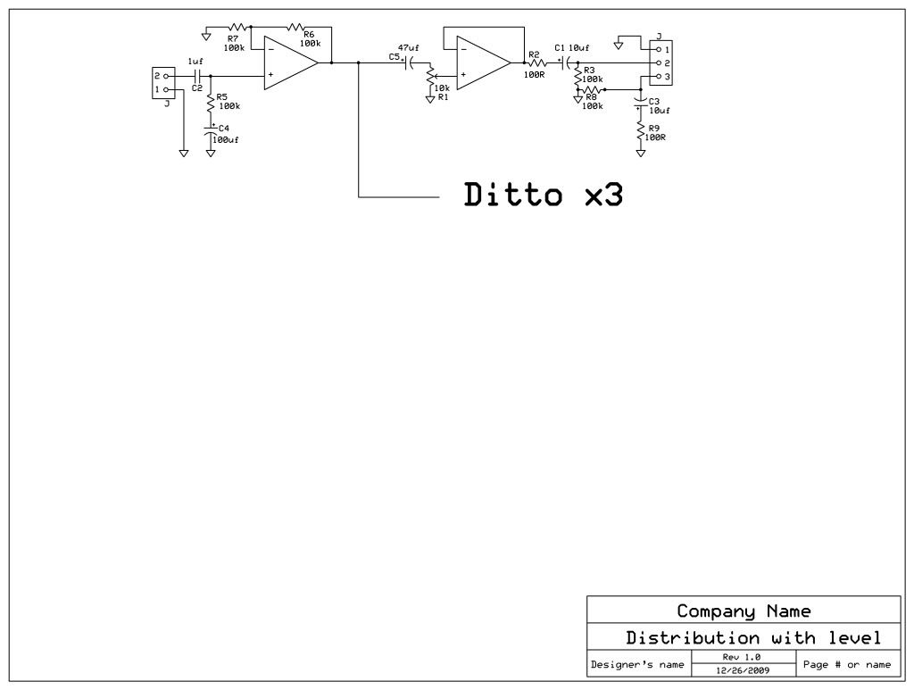
I'm likely complicating everything with too many buffers.  But the initial signal is buffered and sent to 4 opamps.  These each have level controls which are 10k pots on their outputs.  This signal then gets sent to another opamp to be buffered and then is impedance balanced.  I thought this scheme to be good for noise rejection but is also easily compatible (correct me if I'm wrong) with an unbalanced input on a receiving unit.

Essentially, I little clue as to whether the many of the R and C values are correct.  I generally know why they are there but... I'm reasonably green.

Should I/can I eliminate the first set of buffers and replace them with resistors?  If so, what value?

Should I have a low value resistor on the opamp output before hitting the variable resistor/pot?  Does the opamp dislike if the pot is essentially shunting to ground (i.e. no resistor on the opamp output) or off?

Finally, I half thought it might be nice to add some gain somewhere (maybe on the first initial buffer) so the 10k pot could be at say 3/4 up and still add some gain (or the appearance of gain - the gain would actually be fixed earlier in the chain).

Ok... Any thoughts?  Thanks again.

Auxschematic.jpg


CC
 
conleycd said:
I didn't show any of the power wiring for clarity.
Split rail or single rail supply would make a difference.

Should I/can I eliminate the first set of buffers and replace them with resistors?  If so, what value?
yes, nada ohm.

Should I have a low value resistor on the opamp output before hitting the variable resistor/pot?  Does the opamp dislike if the pot is essentially shunting to ground (i.e. no resistor on the opamp output) or off?
No. You know your load conditions here. You then have 4x 10K pots wired in parallel between your 1st. buffer and 0V, representing a 2,500 ohm load for your driving stage. Your DOA/NE5532/OPA2604 will drive this load. A low value resistor in series between your DOA and this load will make it maybe 2,547 ohm. Fit a cap instead to keep DC offset from your pots, else these will get scratchy. This cap with connected shunt (your pots) will build a 1st.order HPF with -3dB cutoff in Hz calculated  1/(2¶ x R x C) with R in ohm and C in farad. A 47uF for 1.35Hz might do, else fit to your needs [1/(6.283 x 2500 x 0.000047)=1.355Hz, same as 1/(6.283 x 2500 x 47 x 10^-6) if you like it better exponentially]

Finally, I half thought it might be nice to add some gain somewhere (maybe on the first initial buffer) so the 10k pot could be at say 3/4 up and still add some gain (or the appearance of gain - the gain would actually be fixed earlier in the chain).
Your pots will have a log law. Depending on manufacturor, the 3/4 up value of this voltage divider will differ.
'Some gain', might be +6dB (voltage gain of 2), could be in your 1st.stage. As drawn, all opamp stages have to be unitygain stable anyway. Voltage gain of a non-inverting gain stage is calculated 1+Rfeedback/Rshunt. Same value (maybe 10K) for both resistors will give you this voltage gain of 2 or +6dB, else fit to your needs but watch parts limits. Any DC-offset in front of your 1st.stage will get amplified by this same amount, so you might need another HPF in front.

C1 and C3 might be decreased to 10uF or even lower. YMMV. Without connected load this 100uF/100K HPF is set for 0.016Hz. A typical connected load in parallel to this 100K might be as low as 10K, giving 100uF/(100K||10K), lifting this -3dB cutoff to 0.175Hz. Decreasing this 100uF to 10uF will shift this cutoff to 1.75Hz, keeping the phase response angle tested down to 20Hz below -5° [-ARCTAN(HPF / testfreq) x 180 / ¶].

just my 2ct
good luck.
 
Hey Harpo,

Thanks for your assistance.  I've posted a revision, but I wanted to explain a bit just so I am sure I understand.  I don't just want a functioning circuit - I hang out here to learn too.  So some answers and then some...

It is split rail (bipolar power supply).

I've eliminated the second buffers.  Now, am I correct that the pot will create a variable HPF depending on what is being shunted to ground?  If that is the case - do all the pots then affect the overall HPF as they are turned?  I realize we are talking mostly about not audible high pass filers here.  The AMZ Fx (pedal effects) little RC filter calculator computes essentially what you have computed (with some rounding) so I think I'm following well.

I've added gain (I was also thinking 6db) in the first stage which will likely be a DOA (not that it matters too much I guess with that load being ok for most ICs to manage - other than any sonic sound improvements).  I added another HPF with the 1uf and the 100k shunt.  I'm not sure I did this properly.  But I calculate the 1uf and the 100k shunt to be around 1.6hz corner frequency - however, with the other 100k for the gain of the opamp I calculated 50k resistance.  So does that raise the HPF to ~3.2hz?  I thought if I used 10k to generate the gain my HPF would rise to be like ~30hz.  That's why I used 100k to form the gain.  Should I have put that first pull down resistor before the 1uf cap?

I understand that any offset in stage 1 would be passed on hence the capacitors before the second buffers.  So I took your advice and added the 47uf caps.

I decreased C1 and C3 to 10uf per your suggestion.  My understanding of this is that the HPF maintains better phase response with this value because it makes the corner frequency 1.75hz which is better than 0.016hz.  Am I right here?  I also understand that this HPF is somewhat dependent on the receiving unit as both capacitance and resistance will change depending on the input impedance of the receiving unit.  I figure if the input impedance of the receiving unit is not great like 10k or something that the HPF is still reasonable.

Finally, is R2 of 100R necessary or should I leave that out?

Thanks so much.

CC

Auxschematicrevised1.jpg
 
A couple of thoughts. First, the buffers after the pots need to be a FET-input opamp, or else you'll need caps between the slider of the pot and the input to block the opamp's bias current. That's the most likely source of scratchy pots.

If you use a low-offset opamp for the first buffer (before the pots) you should be able to eliminate the caps connecting that buffer to the pots.

Are these going to be set-and-forget amplifiers? If so, trimpots would be fine to use.

Finally, the output resistor connecting pin 3 to ground should be 100R, not 100k, to create an "impedance-balanced" output. More correctly, it should be 100R in series with 10uF, that combination in parallel with 100k. Make sure the caps in the pin 2 and pin 3 legs are closely matched. You might want to up them to 47uF and go for non-polarized.

Peace,
Paul
 
Hey Paul,

Thanks for your post.  I'm planning on using a 2520-esq preamp for the first Opamp.  This will be run off of a bipolar supply.  The Opamps after the pots are likely going to be OPA2604 (so they are FET input) - but you're suggesting that something like a NE5532 wouldn't work there?

Nah, they are definitely not set-and-forget amplifiers.  My thought is that these would be used to split signal with level and be sent to external devices or even a mix bus (like you would do for auxes) to be returned at a later stage (if desired).

I revised the input of the first amplifier - specifically the resistors into the inverting preamp because I had the 100k on the non-inverting instead of the inverting to ground.

Yes, the pseudo-balance stage was incorrect wasn't it.  I have corrected that on this schematic.  Good word about the matched caps and resistors.  What advantage is there for a non-polarized cap?

So... (correct me if I'm wrong) if I go 47uf on the cap and the receiving unit is 10k load (?impedance) then the load ends up being 9k or so and the corner frequency is 0.4hz HPF.  If the receiving unit is about 20k then the load is about 16.6k and the corner frequency is about 0.2hz HPF.  For a 10uf cap it is 1.8Hz and 1Hz respectfully (based on those previous load figures cited).  What's the general opinion on this?

To be honest, I have no idea what that HPF corner is best - below say 6Hz or below 0.x Hz?  Harpo suggested that a slightly higher corner than I originally had was a better phase coherent slope (I may have made up that phrase but that is what I think).

BTW: is C4 needed?

So here's the fixed version...

Auxschematicrevised2Example.jpg
 
> am I correct that the pot will create a variable HPF depending on what is being shunted to ground?

No.

What's getting shunted to ground?

At full-down, it is just a 10K load. At full-up, it is 10K in parallel with the op-amp input. What is the input impedance of the opamp? Most chips/modules, naked, will be >>1Meg. Say 1Meg. So your R-C product has 10K full-down and 9.901K full-up. It is usually acceptable to have more bass extension than specified, so you meet your spec on the worst-case 9.9K value. For -3db at 1Hz you need 16.08uFd. A 22uFd or 47uFd +/-20% cap is cheaper than a 16.08uFd cap, and you wonder why you bothered with such fine calculations.

Paul is correct: you may want to cap-couple off the wiper, and then you need a path for the DC current, and for such as 5532 it may like to be near 47K. Now your cap-pot RC varies from 10K to 8.2K. And you have another R-C from wiper to amp, 47K plus the pot impedance which could be zero or 2.5K or 1kK|47uFd. And since you have two roll-offs, you want to aim each one an octave lower to meet a similar final -3dB point.

> I've added gain (I was also thinking 6db) in the first stage

No. you have not. Re-plagiarize basic amplifier configurations.

EDIT -- your new version has gain, or would, except C4 blocks input DC current and that first amplifier will drift to a rail. Re-plagiarize basic amplifier configurations.

And: don't take mystery inputs, raw, and amplify. The fool at the main mixer may send you 7V signal. If you gain-up by 2, you get 14V signal. And +/-15V systems can't do 14V.

If you -know- signals are weak (microphones, phono, heads, pickups), apply gain. If you can be sure someone already gained it up, take it as it comes, unity gain. If you need control, first run it to a pot, then to a little gain.

This is how "I would do it". By raising pots to 100K, we get nominal 25K input, which any modern source will drive. Yes, if all four pots are set full-up, this drops to 8K, which should not distress most sources. And taking a gain of 3 after the pot means the "nominal" knob setting is 4 or 5, and that you usually will not have a pot full-up. I don't believe in "balanced output impedance"; if unbalanced won't do, get balanced.

Yes, I know you have some groovy module you want to use in front, but I don't see any reason to squander a good amplifier as a unity-gain buffer.
 

Attachments

  • conleycd-mod.gif
    conleycd-mod.gif
    6.7 KB
Wow PRR,

Thanks so for your post.  You scare me (in true reverent fear) in all your posts with your immense knowledge on just about any subject area here.  I really appreciate your contributions.

I followed near everything in your post.  I failed to remember that most caps have +/- 20%. 

In your circuit (thanks) would you use something like a OPA2604 for gain of 3 or something more exotic along the DAO lines given that the circuit would not just be a unity buffer any longer.

BTW - In my application I know the signal I'm receiving into this circuit.  It will be from a combining amplifier - a typical plagiarized summing amplifier into the inverting opamp.  But, in my opinion this circuit idea is useful for a variety of applications.

I would be honored to plagiarize your schematic (if that's ok) but I can't make out the value of the capacitor from the wiper into the non-inverting opamp input.

Thanks.

CC
 
> I can't make out the value of the capacitor

So figure it out.

What bass do you want? (Remember that one -3dB at 10Hz network is a mere 1dB at 20Hz, but ten -3dB at 10Hz in a system is -10dB at 20Hz, -5dB at 40Hz, coupld dB at 80Hz, and that starts to hertz your bass-boom.)

What is the resistance? 47K, in parallel with the chip (dang-near infinite), plus 0-25K in the pot. Worst-case, 46+K.

Use your Reactance Table, or PC tools, or work backward from some known R-C bass cutoffs:

1K and 10uFd is 17hz
1K and 100uFd is 1.7Hz
100r and 100uFd is 17Hz
0.01uFd and 1Meg is 17Hz

If you use a PC, you may get "3.45678uFd". If you use a Reactance Chart, you may get "between 2 and 5 uFd". Same answer.

Just like when I calculate my porch joists, the WWJD answer is "3 fingers by one palm" and the BeamCalc says 1.5000" by 4.7890". When you allow for tolerance, and look at available lumber, and costs, you'll see these are both the same answer. The porch gets a standard "2x6" (really 1.5x5.5"), cuz its deeper than a palm, and it's stupid to trim 0.7110" off a stock timber. If it comes out 15.678% stronger than "required", that's OK.
 
Back
Top