efinque
Well-known member
- Joined
- Jan 3, 2018
- Messages
- 393
Sup GDIY,
upon purchasing an Arduino Starter kit I also acquired a solderless breadboard. The MCU now uploaded with code and inside a case I put the breadboard into use (I've been using it for other various projects too w/o the Uno board like filter design etc, iirc the previous platform which came with the kit was brown plastic and had a 9V battery holder but first I cut in half and eventually threw it away because I no longer needed it for the Arduino)

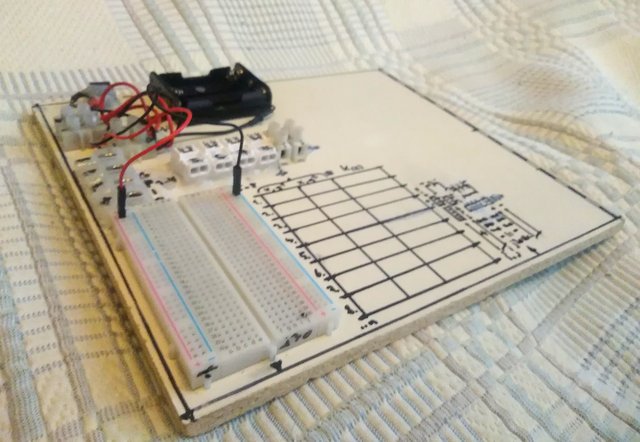
First I cut a sheet of 8mm thick MDF about 210x245mm as the base, then using screws, hot glue and double-sided tape I attached the goodies; a 2,1mm power jack, a 3xAAA battery holder and a +/- screw terminal wired in parallel which are used to supply power to the breadboard. It stands on rubber feet.
The breadboard is 400-point (a to j, 1 to 30) with power bus strips, as I was inspecting it after cleaning it with alcohol, oil and steel wool/sand paper I noticed the other +/- rail shorts and one pin in the breadboard is damaged (not a big deal really as I marked them down)
Then it has a GPIO (=General purpose input/output) consisting of 4 screw terminals and 4 crimp terminal blocks as well as an additional 2-pin screw terminal (10 in total) for interfacing with external modules, input sources, output devices etc because doing so via jumper wires from the breadboard is kind of flimsy and hazardous.
I also drew an 8-column 3-row array as a reminder to keep track of the component wiring. It also has a schematic/block diagram including the board layout.
Is there anything else one would add to it? Power on/off button/LED perhaps, audio jack, more I/O, and/or a fuse holder comes into mind but anything else?
-ef
upon purchasing an Arduino Starter kit I also acquired a solderless breadboard. The MCU now uploaded with code and inside a case I put the breadboard into use (I've been using it for other various projects too w/o the Uno board like filter design etc, iirc the previous platform which came with the kit was brown plastic and had a 9V battery holder but first I cut in half and eventually threw it away because I no longer needed it for the Arduino)

First I cut a sheet of 8mm thick MDF about 210x245mm as the base, then using screws, hot glue and double-sided tape I attached the goodies; a 2,1mm power jack, a 3xAAA battery holder and a +/- screw terminal wired in parallel which are used to supply power to the breadboard. It stands on rubber feet.
The breadboard is 400-point (a to j, 1 to 30) with power bus strips, as I was inspecting it after cleaning it with alcohol, oil and steel wool/sand paper I noticed the other +/- rail shorts and one pin in the breadboard is damaged (not a big deal really as I marked them down)
Then it has a GPIO (=General purpose input/output) consisting of 4 screw terminals and 4 crimp terminal blocks as well as an additional 2-pin screw terminal (10 in total) for interfacing with external modules, input sources, output devices etc because doing so via jumper wires from the breadboard is kind of flimsy and hazardous.
I also drew an 8-column 3-row array as a reminder to keep track of the component wiring. It also has a schematic/block diagram including the board layout.
Is there anything else one would add to it? Power on/off button/LED perhaps, audio jack, more I/O, and/or a fuse holder comes into mind but anything else?
-ef


