Long ago, back in page 2
here,
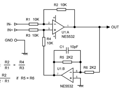
@thor.zmt mentioned (and explained) the "double inverted" topology with front buffers added (and that trick to tighten resistor tolerance for better CMRR) as a better implementation for lower noise.
My question is: how does it compare to a standard instrumentation amplifier, and why the "double inverted" is better, noise-wise? The "double inverted" uses 4 op amps, whereas the instrumentation amplifier uses 3 - one less active part hissing away on our signal, or so it seems for my untrained eyes.
IF ALL ELSE = ALL ELSE
Instrumentation has ~3dB less noise, IF Op-Amp noise is absolutely dominant and resistor noise is minimised. And SuperBal has less noise than Instrumentation.
As the TL07X has 18nV|/Hz Ein this is given. In 2024 there is zero justification to use such a poor part.
On the other hand, the "mixing amp" in the dual inverted option operates at zero common mode, which may result in lower HD, less EMI sensitivity etc.
Also we do not get many triple Op-Amp's, but Quads and Dual's you now have a spare OPA looking for a job.
The TL07X is a utter tosh part for audio in 2024, well it also was in 1985. Swap them out for OPA1679, which in turn is a symbolised OPA1654 with less testing and possibly lesser binning on DC Offset and some other parameters. In practical use I found OPA1679 = OPA1654.
Ein is 4.5nV|/Hz at 1kHz or 12dB less than TL07X, 3V into 600 Ohm gives -120dB THD & N. Price in 1kU is 40 cent USD for the Quad. Or 10 Cent per OPA.
Also, switch TINA output for noise to SNR, bandwidth 20-20k, reference level 0dBm (0dBu = 0.775V) for dBm/u reading or 1V for dBV or expected operating level for actual SNR @ operating level.
I should add something. My own use of Balanced connections is somewhat unusual. I actually happen to think that most of the time balanced connections are utter tosh and worse than SE, UNLESS REAL TRANSFORMERS ARE INVOLVED AT BOTH ENDS.
So my balanced connections are all modified to look like this (one or the other version):

And usually the connection is switched to SE.
Personally, in 99% conditions in a small studio or domestic setup, there is no advantage to Balanced connections, instead of (barely) hiding earth/ground loops inside the CMRR of a balanced input, simply sort this out properly and there is no need to hide something not there.
I content that the above Circuit, in SE mode or in Balanced is the lowest noise option and usually also lowest distortion option.
The theoretical drawbacks may be relevant in stage gear or something sold to non-technical pee-pull, in our own studio or home they should not be.
I am sure we could promote the original OC71 transistors as 'the best thing since sliced bread' for Hi Fi use and many would fall for it because they are Germanium transistors.
Actually it is NOS 12AX7, Telefunken Smooth Plate Tube, not Geranium Transistors.
Thor


 , anybody interested?