Douglas Self Line Input compared to Mackie line input

GroupDIY Audio Forum

Help Support GroupDIY Audio Forum:

This site may earn a commission from merchant affiliate links, including eBay, Amazon, and others.
so if I understand correctly, we are talking about two different aspects: CMRR and "inherent" circuit noise:
CMRR is improved using precision resistors or ICs like THAT 1240. If you also want high CMRR when there could be impedance mismatch between driver and receiver, than THAT "InGenious" solution is even better.

The impedance difference relevant to the CMRR is that between the input legs. Difference here reduces the CMRR.
The higher the Common Mode input impedance the less effect any difference has. A transformer input offers very high common mode input impedance. The Ingenius and other similar topologies seek to replicate this impedance via a form of "bootstrapping".

Aside from CMRR, the circuit proposed by Mackie or by Self that I linked on post #1 are inherently noisier than the "double inverted" configuration, when adjustable gain is needed.

Without running the numbers I read the Self Circuit as being quieter than the Mackie.
Resistor values can be adjusted to change the noise but that can lead to issues with current demand (limits and heat dissipation) and input impedances.
 
what I meant with wiring the Dir Output directly to the Line in was something like this:
View attachment 117857
I'm trying to understand what is the difference with a (impedance) balanced output like shown before and this simple connection

The Impedance balanced output is buffered and does not load the source. The second scheme has the load of the soundcard in parallel to the line in and depending on design in the sound card might limit permissible levels etc.

Thor
 
so if I understand correctly, we are talking about two different aspects: CMRR and "inherent" circuit noise:
CMRR is improved using precision resistors or ICs like THAT 1240.

Correct.

CMRR (Common Mode Rejection Ratio) is only relevant where the system experiences a lot of common mode noise.

In most cases this is not a problem in studios or even live sound with normal length shielded, twisted cables. So the resistor mismatch is not very critical in this case.

The extra precision of the "laser trimmed" resistors inside IC's is thus of limited value.

Modern 1% tolerance SMD thin film resistors on a reel usually are much better tolerance on average.

You can also use multiple resistors in parallel to further improve matching. Like say instead of 12k/6k (as found in most THAT) you use two sets each of 4 X 47k in parallel and 4 X 24k in parallel. This way you get much better than 1% in practice accuracy. Done SMD the cost increase is very nominal.

If you also want high CMRR when there could be impedance mismatch between driver and receiver, than THAT "InGenious" solution is even better.

Let rephrase this. In the real world, where the output resistors in your source and the cable resistances are not laser trimmed to 0.01% tolerance you are bound to find that very high CMRR of an expensive IC is degraded to something just as bad as the discrete circuit with 1% tolerance resistors.

There are options to improve this situation with considerable increase of circuit complexity, if very high real world CMRR is really a necessary design goal.

Aside from CMRR, the circuit proposed by Mackie or by Self that I linked on post #1 are inherently noisier than the "double inverted" configuration, when adjustable gain is needed.

The Mackie Circuit is relatively noisy because of the relatively high resistor values and because the second stage (in 0dB setting) first attenuates the signal by around 10dB (while noise remains static) and then amplifies the signal AND noise by the same 10dB.

The Circuit by Mr Self mainly has poor gain control characteristics, if designed with sensible impedances. There is a lot of "interactivity" between gain and impedances. Noise is much better than Mackie, but probably still worse than double inverted, if we moderate load impedance's for the Amplifier output and keep the the input at ~10kOhm balanced.

The "double inverted" configuration decouples gain and balanced in completely.

The actual output amplifier is basically an inverted amplifier where we can set both gain and attenuation with one resistor in the feedback loop, without ANY effect on CMRR. So we are free to design our gain control absolutely freely.

Further, because the output amp is in effect a mixer amp and the second phase is inverted and added to first, we have lower value feedback resistors (less noise) and when we attenuate we also reduce circuit noise by the same amount. And because we use all op-amp's inverting, any common mode induced distortion doesn't happen in the first place.

BTW, I only recommend this circuit is the goal is a single ended output, wide range gain adjustable circuit with balanced input.

I also noted your other thread: help me understand differences between THAT line receivers for ADC

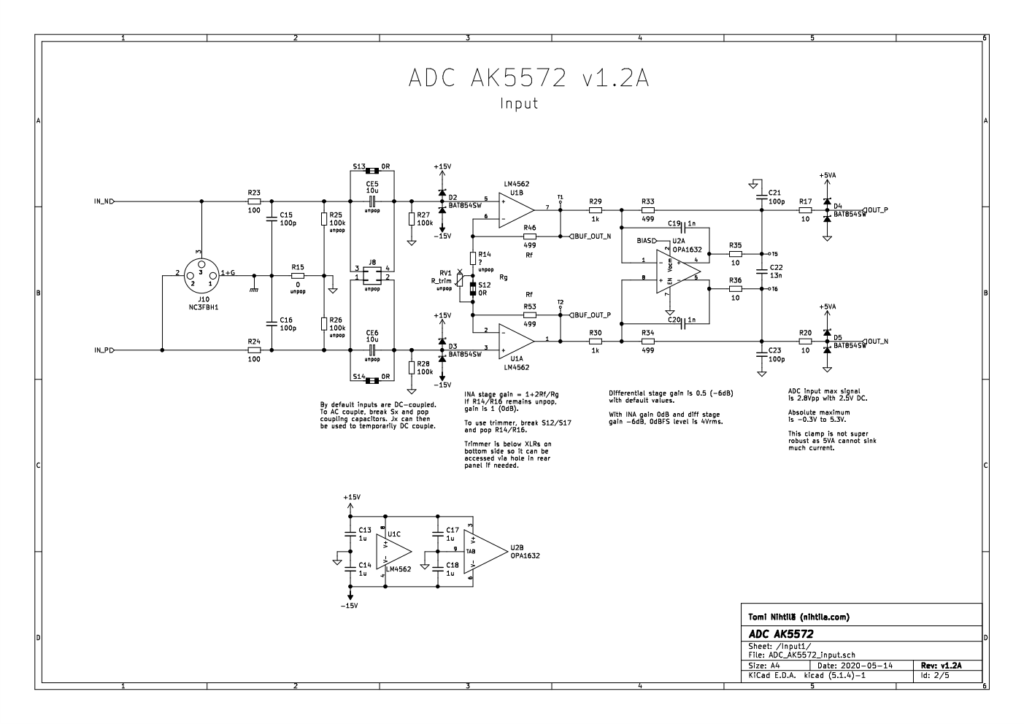
I would suggest that the "gold standard" for a balanced in, balanced out to drive ADC circuit uses either a "Fully Differential Amplifier" in "active attenuator" configuration, something like this(second part):
ADC_AK5572_v12_input-1024x724.png
Pretty much any modern ADC works best from the lowest possible impedance and requires capacitors on direct input to avoid switching glitches from the ADC circuit to impact the analog stage. This circuit delivers this.

As alternative, the FDA can be be replaced with a conventional Op-Amp (dual or two singles) in the Birt circuit.

Thor

PS, as an outside bet, you can use high grade transformers for Line Input and to feed an ADC from a line. Done right and with sufficiently high quality transformers the results can exceed of active electronics, as a massive cost increase.
 
Last edited:
Ok, up to now we have looked at design principles.

Let's instead have a fully elaborated design, such as I might recommend to a client who needed a low noise, low distortion, low cost, high real world CMRR, balanced Input and SE output circuit for say a Mixer, Audio Interface or Active monitor. It is still based on the "double inverted" topology, but further optimised.

1701506077368.png
First, the inputs are now buffered. This gives an 500kOhm // 20pF common mode input impedance.

Second, the resistors in the circuit have been reduced to 2.05kOhm and are made up out of four parallel resistors. This reduces the noise by another ~ 3dB over the use of 4.7kOhm. There is ultimately a tradeoff between low value resistors to reduce noise and avoiding to load the amplifier circuitry such that HD is increased unacceptably.

IN THEORY we could use multiple parallel input Amplifiers with individual feedback loops and output resistors and parallel amplifiers everywhere, but to get a 6dB improvement in noise we would need four times the various parts. Instead discrete high current buffers (or IC's) could be used to allow the use of much lower resistor values. Eventually the Op-Amp noise will dominate.

The parallel resistors improve guaranteed tolerance by the square root of the number of resistors used, assuming a gaussian distribution of tolerance. Now in reality, for 99% of all circuits of these assembled from a reel of resistors the actual mismatch is going to be much better than that.

With a guaranteed 0.05% mismatch if using commodity priced 0.1% Tolerance Thin Film SMD resistors the worst case CMRR should be ~66dB, in practice I'd expect > 80dB for MOST of the circuits made on an assembly line.

The Op-Amp is a recent TI type that is a much better choice than either 5532 or TL074, I picked the quad as it allows a single package for the receiver circuit.

Resistors are assumed "Royalohm" Brand Thin Film in 0.1% tolerance and 0603 package. Small Value capacitors should be C0G in 0603 (e.g. Samsung) or at least X7R for 100nF, the 100u Capacitors, any generic type will do, 25V suffices for all capacitors. +/-18V supplies are presumed.

You can add input and output coupling capacitors to the circuit if so inclined. For the inputs 1uF film capacitors will limit increased noise and CMRR reduction. On the output it will depend on the following stage. As is DC offset will normally at 1mV or less using the specified op-amps.

The 1kU BOM cost of this circuit would be in the region of 2 USD due to the cost of the Potentiometer. If using (say) a resistor chain and an 11 position switch which allows 4dB steps cost is up some more, but reliability of repeatable adjustments and overall subjective sound quality are likely improved.

By comparison a THAT1240 in 1kU calls down 2.40 USD and you still need to add a lot of budget for passives, gain adjustment etc. for a best case SNR that is 6dB worse and around ten times worse (T)HD.

Of course, the Mackie or Self input will be cheaper, but by how much would need to be seen.

So realistically, "canned" receivers are not competitive commercially. They make some sense for DIY if you hand solder (if on the other hand you order a fully stuffed SMD PCB from JLCPCB et al there are better options.

Thor
 
Last edited:
thank you really much Thor, that is really informative and valuable! I will surely use this approach

some questions, to better understand:

1) how this approach compares to the "standard" instrumentation amplifier? I guess the main difference is that an instrumentation amplifier cannot have gain less than unity, unless you reduce gain in the first stages and then add gain when needed, with a noise penalty (as we saw at the start of the topic) compared to dual inverted approach you showed.

2) what approach would you choose if no gain control would be needed, and unity gain is required?

I am asking this because I am building is a little mixer/console for my own use.
It will have a pair of line inputs (no mic inputs needed).
The first input, used to monitor and record, will need variable gain and direct out going to the audio interface. I will use your approach here.
The second line input will be with fixed (at unity?) gain, used as "tape return" for mixing (coming from the audio interface DAC outputs).
 
FWIW, I've never used balanced for line level, and have never in decades of use picked up slightest bit of noise. I always use cables with braided shield, and have run as long as 75'. Occasionally use served shield cables (Mogami) - never any noise with these either.
 
Let rephrase this. In the real world, where the output resistors in your source and the cable resistances are not laser trimmed to 0.01% tolerance you are bound to find that very high CMRR of an expensive IC is degraded to something just as bad as the discrete circuit with 1% tolerance resistors.
Yes but I'd take a closer look at the math with a realistic value of build-out.

A THAT1246 with internal 50 ppm resistor match has about 86dB CMRR.
I did a quick calculation of how much a 1% 49.9Ω build-out would degrade CMRR and I come up with 6 dB degradation.
If both build-outs were off in opposite directions 12 dB degradation.
As I said my calculation was quick - even if its 24 dB degradation 62 dB CMRR is a along way from the 35-40 dB CMRR of 1% resistors.
Larger build-out values make a 1% mismatch worse.
 
As I said my calculation was quick - even if its 24 dB degradation 62 dB CMRR is a along way from the 35-40 dB CMRR of 1% resistors.

Given that 0.1% Tolerance resistors by the reel run at around 3 cent USD from Mouser using 1% is not useful in this circuit. For a typical case 0.1% Resistors in the classic balanced receiver offer 54dB absolute worst case CMRR and and over 75dB typical. And the risk of the worst case is less than 1 in 500.

Here the CMRR in the THAT Datasheet:

1701612309299.png

Here an interesting article which among other things contains an actual measured CMRR of the circuit using unselected 1% resistors:

1701612379569.png
1701612343865.png

https://www.edn.com/variable-gain-superbal-circuit-preserves-cmrr/

The observed CMRR @ 60Hz is better than the worst case in the THAT Datasheet.

As I noted, paralleling multiple 0.1% resistors improves the result to well past 60dB CMRR and it further reduced the risk of a worst case dramatically as now we would have to (in the circuit I presented) have 16 Resistors all accumulate tolerance into the worst case direction, something which starts to be better than 1 in 250,000.

So, using multiple cheap 0.1% tolerance thin film resistors in parallel can easily approach the typical and worst case performance of the THAT (and other) receivers with trimmed on chip resistors.

The freedom to select the Op-Amp's according to budget and performance requirements and to optimise the noise of the circuit by freely selecting resistors are strong arguments against the use of "canned" receivers.

Where ease of use and lack of need to apply actual engineering is preferred (canned receivers merely require copy/paste engineering) and the performance of canned receivers is adequate they offer a good choice. DIY Audio is an example where a fairly casual DIY'er may prefer a canned receiver plus minimal external parts over a more complex solution.

It all depends on defining one's requirements clearly and then meeting them.

Thor
 
1) how this approach compares to the "standard" instrumentation amplifier? I guess the main difference is that an instrumentation amplifier cannot have gain less than unity, unless you reduce gain in the first stages and then add gain when needed, with a noise penalty (as we saw at the start of the topic) compared to dual inverted approach you showed.

Well, as I stated, we have a few potential improvements.

If we take the fully elaborated circuit, with paralleling of inexpensive precision resistors, we get a CMRR that is as good as any commercial chip, has great resilience to source impedances imbalance and has lower noise and HD.

I do not want to bring subjective sound quality into this, so read between the lines.

2) what approach would you choose if no gain control would be needed, and unity gain is required?\

Well, first I would consider if I need traditional "industry compatibility".

Then if we need an SE output or Balanced.

Then if we really have a need of very high CMRR (not if it would be a good ting, but if it offers any real world benefit.

As almost any line out I can think of can drive 600 Ohm well enough and as modern Op-Amp's drive 600 Ohm loads without trouble, I would consider if I do want very low noise or if it is not required.

Depending on the answers I would select a suitable double-op-amp (likely OPA1656) and implement the double inverting circuit (SE Out) or Birt circuit (Bal Out) with ~ 600 Ohm resistors if low noise is foremost and ~2k resistors if we can relax noise requirements.

Maybe like this?

1701615592428.png
I am asking this because I am building is a little mixer/console for my own use.
It will have a pair of line inputs (no mic inputs needed).

I think to me the greatest question here would be how I am building. Vero Board? Make dedicated PCB's? How much SMD will be used?

The first input, used to monitor and record, will need variable gain and direct out going to the audio interface. I will use your approach here.

Define how wide a gain range you need first. And consider just how much CMRR you really need.

The second line input will be with fixed (at unity?) gain, used as "tape return" for mixing (coming from the audio interface DAC outputs).

The same circuit will work fine, just replace the potentiometer with a fixed value resistor. Or keep the gain trim anyway.

Thor
 
1% was your choice of tolerance not mine.

Yes, typical CMRR with 1% tolerance resistors is 60dB or better based on theory.

We saw that a generic balanced input circuit (Birt type) made with unselected 1% resistors came in at 77dB @ 60Hz. This is about real world CMRR performance of a typical circuit.

As I said my calculation was quick - even if its 24 dB degradation 62 dB CMRR is a along way from the 35-40 dB CMRR of 1% resistors.

Your claim of 34-40dB CMRR is based on "worst case" and not "typical in practice". In practice the difference between the THAT1246 (70dB guaranteed, 90dB typical for 0 Ohm source impedance mismatch) and a discrete implantation using 1% (say 77dB typical using modern quality parts) will degrade to a very similar result.

Past that, let's see what range of source impedance imbalance THAT consider reasonable:

1701616779161.png

I stand by what I originally said based on the choice you made for your argument.

Based on the evidence I presented I stand by the original argument, for a "typical" (as opposed to worst case) circuit.

Your argument as presented is deliberately slanted by presenting a "worst case" condition as "typical", as in "a typical differential line receiver with 1% resistors only gives 34 -40dB CMRR" which is incorrect, as we can see that a REAL circuit with unselected 1% tolerance resistors performs substantially similar to what THAT claims for their circuit.

So I think you need to revise what you wrote.

Past that I merely added that while the "mackie" circuit, which the OP presented, showed 1% resistors (which is what I referenced in my argument), it would be unnecessary to limit oneself to 1% tolerance resistors or single resistors.

So my main rejection of your argument is based on "the 35-40 dB CMRR of 1% resistors" being incorrect for a typical case.

Thor
 
I know the thrust of this thread is adjustable gain but I can't stand by and let real-world CMRR and its importance be trivialized. Noise rejection is, after all, the reason we use balanced interfaces in the first place! Input impedances on the order of 10 kΩ per leg are far too low. In real-world systems they will produce unpredictable and low noise rejection. These impedances need to be 1,000 times higher (10 MΩ or more) to have noise rejection comparable to a good input transformer!

I've attached two papers about the InGenius (R) circuit I patented in 1996 and was licensed to THAT Corp to be sold as the 1200-series ICs. Apparently, Doug Self only became aware of the InGenius circuit after writing several of his books (years after I published the papers). But I think he'll at least mention it in his newest. Perhaps a case of NIH (not invented here) bias - as I encountered when trying to license the circuit to Analog Devices and Burr-Brown back in the day!
 

Attachments

  • InGenius Original 1996 AES Preprint - Whitlock.pdf
    438.9 KB · Views: 2
  • InGenius 2004 AES Paper - Whitlock-Floru.pdf
    380.5 KB · Views: 3
Well, first I would consider if I need traditional "industry compatibility".

Then if we need an SE output or Balanced.

Then if we really have a need of very high CMRR (not if it would be a good ting, but if it offers any real world benefit.
I need it to be SE output. About industry compatibility I can't answer, I haven't yet studied whether there is a standard of levels between the various audio interfaces. This input is going to be connected mainly to the audio interface (not one in particular yet) outputs. Probably with a DB25 connector, so I guess not long cables and no very high CMRR needed

I think to me the greatest question here would be how I am building. Vero Board? Make dedicated PCB's? How much SMD will be used?
it will be built on a dedicated PCB using SMD (probably 0603 for passives, SOIC for ICs)
 
I need it to be SE output. About industry compatibility I can't answer, I haven't yet studied whether there is a standard of levels between the various audio interfaces.

Ok, let me enlarge.

Example, FDA or Birt Circuit (which is really an FDA made from two Op-Amp's) will give you both a balanced and/or two opposite polarity SE outputs. So you can choose.

The Dual Inverter Output is much more easily gain adjusted, but is SE out only. Of course, if we add more Op-Amp we can make it also to have two opposite polarity SE output, or a BAL Out.

When I say "industry compatibility" I mean the overall system, not just levels and I mainly refer to way of doing things, selecting output impedance's, input impedance's etc.

What I'd call industry standard is baked into these two IC's:

1701948891433.png
1701948920307.png

There are updated options, but in a lot of ways these are still "gold standard".

Daisy-chained with +/-18V supplies they are unity gain driver in to receiver out and can handle around +22dBu without clipping.

There are various selections in impedances, circuit structure etc. that limit noise, distortion and CMRR.

If we can avoid follow these "standards" we can make different choices.

For example, when I modified my Yamaha 01V96 I made all outputs impedance balanced, with a much simplified circuit and IC's that find driving 600 Ohm trivial. Then receiving circuits can be lower impedance and we have a much lower noise system.

Usually, if we make our receiver input impedance 600 Ohm most pro audio gear can drive it trivially, if we do 600 Ohm per phase we can use two receivers in parallel and still have no problems.

Going in the above receiver from 12K to 680 Ohm (and 6k to 330R) will give > 12dB lower self noise, as example.

Combine with a high drive, SE Out impedance balanced driver we have a very low noise and simple circuit.

Of course, Mr CMRR will be scandalised.

But I have gear with 0dB CMRR (SE) that handles 120dB dynamic range, so the need for high CMRR is IMNSHO overstated.

Thor
 
Ok, up to now we have looked at design principles.

Let's instead have a fully elaborated design, such as I might recommend to a client who needed a low noise, low distortion, low cost, high real world CMRR, balanced Input and SE output circuit for say a Mixer, Audio Interface or Active monitor. It is still based on the "double inverted" topology, but further optimised.

View attachment 117928

Thor, about this schematic, which components (if any) need to be as close as possible to the input jack/XLR? I've seen schematics with capacitors that need to be as close as possible to the input connector, and tied to the chassis ground
 
Thor, about this schematic, which components (if any) need to be as close as possible to the input jack/XLR? I've seen schematics with capacitors that need to be as close as possible to the input connector, and tied to the chassis ground

I would probably split capacitors and add ferrite beads between to help EMI resistance. Physical implementation and layout is a whole other can of worms...
 
Lowering the values in a simple diff-amp from 12 kΩ / 6 kΩ to 680 Ω / 330 Ω to lower noise makes a horrific sacrifice. What seems to be missed, by Thor and others, is the importance of the highest practical common-mode input impedance in a balanced line receiver. Consider that all the ultra-precise laser-trimming of those four resistors produces the advertised CMRR only when driven by equally-precise balanced sources. In fact, most are tested for CMRR by tying the two inputs together - which makes the differential source impedances zero! Of course they'll perform great, even the ridiculous 680 Ω / 330 Ω values. But, if you do a bit of calculation, you'll find that the slightest imbalance in the common-mode source impedances seriously degrades CMRR. The lower the receiver's common-mode input impedances are, the worse the degradation becomes. The 680 Ω / 330 Ω receiver would lose significant CMRR due to contact resistance variations in cable connections, which are typically in the tens of milli-ohms! Ever wonder why a good input transformer used as a balanced line receiver is so forgiving of what's driving it - in terms of noise rejection? It's because the transformer's common-mode input impedances are in the tens of mega-ohms - a thousand times higher that even standard diff-amps using 10 kΩ resistor sets (see attached Fig 4 from my 1996 AES paper about InGenius). That realization is what inspired the invention of InGenius, which imitates that property of the best input transformers.
 

Attachments

  • CMRR vs Zcm vs Source Imbalance - InGenius 1996 Whitlock AES Paper.pdf
    36.1 KB · Views: 2
Lowering the values in a simple diff-amp from 12 kΩ / 6 kΩ to 680 Ω / 330 Ω to lower noise makes a horrific sacrifice. What seems to be missed, by Thor and others, is the importance of the highest practical common-mode input impedance in a balanced line receiver.

ONLY IF there is a material common mode error signal is actually present. But is it, in a reasonable modern system?

I do not miss the degradation in CMRR. Instead, in a system with a competent arrangements for earth/ground while maintaining agency Compliance, CMRR is not a meaningful figure of merit. So it CAN be compromised, knowingly in this context.

Of course, if we expect a LOT of common mode noise (say 60V RMS) CMRR becomes the most important metric for SNR.

Note that I showed earlier a circuit with very high common mode impedance, using extra followers, that could of course be reconfigured for something like "InGenius".

But if we have only 0.775mV (-60dBu) common mode noise and 40dB actual in system CMRR with a +22dBu signal levels, do we have a problem?

We get 122dB SNR on the significanct common mode noise.

Depending on the situation of the actual system, CMRR may be unimportant or very important.

If in my own set-up, which I make myself , for my own use, there is not enough common noise to degrade my systems SNR, do I need to design for high CMRR anyway, or can I freely choose alternate tradeoffs?

If high CMRR needs a loft of extra circuitry and cost/effort, but no material common mode noise is present, why not simplify?

Thor
 
Lowering the values in a simple diff-amp from 12 kΩ / 6 kΩ to 680 Ω / 330 Ω to lower noise makes a horrific sacrifice. What seems to be missed, by Thor and others, is the importance of the highest practical common-mode input impedance in a balanced line receiver. Consider that all the ultra-precise laser-trimming of those four resistors produces the advertised CMRR only when driven by equally-precise balanced sources. In fact, most are tested for CMRR by tying the two inputs together - which makes the differential source impedances zero! Of course they'll perform great, even the ridiculous 680 Ω / 330 Ω values. But, if you do a bit of calculation, you'll find that the slightest imbalance in the common-mode source impedances seriously degrades CMRR. The lower the receiver's common-mode input impedances are, the worse the degradation becomes. The 680 Ω / 330 Ω receiver would lose significant CMRR due to contact resistance variations in cable connections, which are typically in the tens of milli-ohms! Ever wonder why a good input transformer used as a balanced line receiver is so forgiving of what's driving it - in terms of noise rejection? It's because the transformer's common-mode input impedances are in the tens of mega-ohms - a thousand times higher that even standard diff-amps using 10 kΩ resistor sets (see attached Fig 4 from my 1996 AES paper about InGenius). That realization is what inspired the invention of InGenius, which imitates that property of the best input transformers.

Yes. But Thor's 'thing' seems to be that CMRR is not so important. So you're coming at this from different priorities and unlikely to meet.
fwiw I'd say Thor might have a point wrt simple setups eg domestic hi-fi. But once you get into as anything more complex eh a recording studio / mixing desk setup with all the associated interconnections then CMMR becomes critical.

I see I just crossed post with Thor btw.
 

Latest posts

Back
Top