Dual channel tube mic preamp in 1 RU format

GroupDIY Audio Forum

Help Support GroupDIY Audio Forum:

This site may earn a commission from merchant affiliate links, including eBay, Amazon, and others.

Holger

Well-known member
GDIY Supporter
Joined
Jun 11, 2006
Messages
893
Location
Hamburg, Germany
dtpfro.jpg


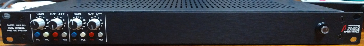
My studio mate asked me to build a dual channel tube mic pre in 1 RU with internal PSU, so everything must fit in an enclosure of 40 mm height.
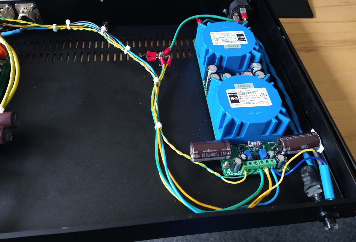
For the amp card it seemed to be managable, but I didn't had an idea for the PSU. Since I had no time to design an own PCB I stumbled over Joe Malone's Scorpion
PSU kit. I gave it a try. After a mail conversation with Joe, who responded fast and comprehensive, the Scorpion worked as expected.

dtppsu.jpg


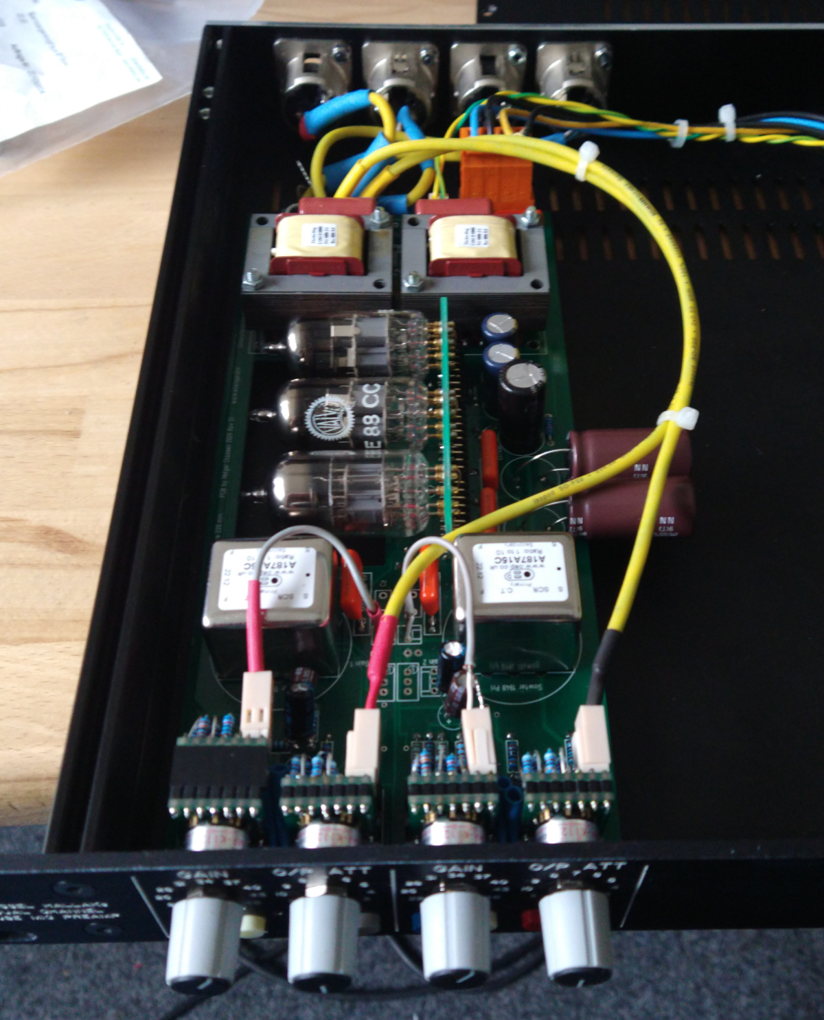
The amp card is the same as in my modular system, it's Ian Thompson-Bell's TLA built as mic pre.
Stepped NKK switches for Gain and O/P attenuation. Found some new old stock Hamburg made Valvo E88CC. Enclosure is from Modushop.
The mic pre works excellent.

dtpamp.jpg
 
Beautiful work Holger. I have thought about making tube sockets using the Harwin or Millmax pins and had wondered how tight the sockets would be but looks perfect :)
 
Beautiful work Holger. I have thought about making tube sockets using the Harwin or Millmax pins and had wondered how tight the sockets would be but looks perfect :)
I first noticed them being used in a 500 series tube module many years ago and decided to give them a try. They work surprisingly well. I would not use them if the device was going to be bounced around a lot but otherwise they are very effective. The biggest problem I find is consistency of hole size between PCB manufacturers using the same Gerber data. Sometimes the pins are a very tight fit and others they are quite slack. Be aware they are two basic types of these pins; plain and knurled. I initially used the knurled ones because they made a nice tight mechanical fit with the PCBs I was using at the time. But when I changed manufacturer I sometimes could not get them in. So Now I use the plains ones. These are always a slck fit so I populate the sochet with pins and then plusg in a tube to hold them all in the correct relative postions whilst I solder the pins.

Cheers

Ian
 
Nice work Holger ,
I suggest adding a nylon P-clip on a pcb mount standoff to support the large brown electroytics .
 
I first noticed them being used in a 500 series tube module many years ago and decided to give them a try. They work surprisingly well. I would not use them if the device was going to be bounced around a lot but otherwise they are very effective. The biggest problem I find is consistency of hole size between PCB manufacturers using the same Gerber data. Sometimes the pins are a very tight fit and others they are quite slack. Be aware they are two basic types of these pins; plain and knurled. I initially used the knurled ones because they made a nice tight mechanical fit with the PCBs I was using at the time. But when I changed manufacturer I sometimes could not get them in. So Now I use the plains ones. These are always a slck fit so I populate the sochet with pins and then plusg in a tube to hold them all in the correct relative postions whilst I solder the pins.

Cheers

Ian
I've done that, too. Used on 9 pin power tubes which can crack the glass base as the tube gets hot as everything expands. On miniature 7 and 9 pin it will probably work. Keep in mind regular tube socket have very flexible contacts that can accommodate bent pin and give as tube changes temperature. Some of those mill pins have little wiggle room in each pin socket.

That's my story and I'm sticking to it!
MR Moscode
 

Latest posts

Back
Top