Dual Mila preamp.

GroupDIY Audio Forum

Help Support GroupDIY Audio Forum:

This site may earn a commission from merchant affiliate links, including eBay, Amazon, and others.
Question about resistors:

I wanted to use Dale CMF55 (RN55) resistors, but they have working voltage rating of 350V.
Should I use CMF60 (RN60) series - 500V working voltage instead?

The schematic tells nothing about resistor voltage rating. The voltages don't exceed 300V - however, caps must be 400-450V rated.
Or is it just better to use higher ratings?
 
I would not expect any of the resistors to ever sustain 350V so those types should be fine. Capacitors should be rated for the voltage they will sustain plus an engineering margin.

Cheers

Ian
 
ruffrecords said:
I would not expect any of the resistors to ever sustain 350V so those types should be fine. Capacitors should be rated for the voltage they will sustain plus an engineering margin.

Cheers

Ian

Thank you, I'll go with RN55 then.

I ordered 2HU enclosure and some other stuff, like knobs from Musikding.
Slowly, I'm getting there  :)

Btw, finding cool font for the front panel took some time. This one looks very similar to what we are used to see on vintage equipment. I hate when panel work looks something straight out of MS Office.  ::)

It's a free font, google "Bebas Neue".

Mila_Schematic7.png

 
Small update and question:
I have ordered/received almost all components. Don Audio however, has a huge delay with Mila transformer (ordered month ago, still not shipped). They said they can ship audio transformers I ordered now, and Mila transfo later.
Axial caps are nice and bulky, I like that.  :) Very nice "jewel lamp" and toggle switches too.
I think it is going to be a thing of beauty when it's finished  ::)

Now I have everything, except XLR connectors and rotary switches for gain range - I will ordered them from Mouser.

The question is - are switches supposed to be shorting or non-shorting (for gain)?
Also - is there any downside to power switch being SPST (I already have a really nice one SPST switch)? I see a lot of schematics with just a SPST switch (as the original Mila schematic), but something tells me, that it would be better for disconnect the preamp from mains completely, with DPST switch.
 
Update:
Received all the parts. Some stuff is not good though, so I will have to do another eventually.
But for 99% it's all there - so I'm building this thing.

Here is the turret board I made for the PSU.

IMG_4232.jpg

Unfortunately, I don't have my miter saw right now, so not a straight cut :( I'll use it for the preamp board though.

First problem: I doubled the value of C1, C2, C3 (the original PSU is designed for 1 preamp, I presume). C1 and C2 are for the low pass filtering, so why not ... but I'm not sure what C3 does. Was this a good decision?
But, for some reason I didn't double the wattage on R1 and R2  :eek: should I make it 4W? After making some calculations, I think it could be a problem (not that I'm good at calculating this stuff).

mila_psu.png

 
Hi,

R5 and R6 are elevating the virtual center tap (R3+R4) of the heater on a higher potential than ground.
C3 is there to decouple this potential from HT(here 329V). You can leave it as it is.

Don't worry about R2, it is just a bleeder to discharge C1 and C2 when you switch off your PSU. This is for your safety! There is very low current at this point, so 2 Watt for R2 is enough.

With the values NYDave gave us in the schematic R1 would be big enough for two channels. 4 Watt would be better.

For my taste the ripple reduction for two channels is too low, even with the double capacity for C1 and C2.
I would exchange R1 for a decent 10H choke.

Hope that helps and my humble english is good enough... :D

cheers
 
rock soderstrom said:
Hi,

R5 and R6 are elevating the virtual center tap (R3+R4) of the heater on a higher potential than ground.
C3 is there to decouple this potential from HT(here 329V). You can leave it as it is.

Don't worry about R2, it is just a bleeder to discharge C1 and C2 when you switch off your PSU. This is for your safety! There is very low current at this point, so 2 Watt for R2 is enough.

With the values NYDave gave us in the schematic R1 would be big enough for two channels. 4 Watt would be better.

For my taste the ripple reduction for two channels is too low, even with the double capacity for C1 and C2.
I would exchange R1 for a decent 10H choke.

Hope that helps and my humble english is good enough... :D

cheers

Thank you,

So it would be even better to replace C1 and C2 with let's say 80uF (or even more?)

And replace R1 with a 10h choke - like this one? http://www.mouser.be/ProductDetail/Triad-Magnetics/C-7X/?qs=sGAEpiMZZMv126LJFLh8y%2fbhSeFmneKH3NJuXlNAsvE%3d
Or maybe this one? http://www.tube-town.net/ttstore/Transformer/Chokes/Hammond-193-Series/Hammond-Drossel-193B::85.html (or other one maybe? Not an expert on chokes  :( )

Now that you mentioned English isn't your native language, I can't help it but to read your post with German accent  ;D
 
"Now that you mentioned English isn't your native language, I can't help it but to read your post with German accent  ;D"

LOL, but thats very close to reality! 8)

If you use a choke instead of R1, then you dont need to increase C1 and C2 but your HT will be bigger. Check this simulator to get a picture about whats going on in your PSU.  http://www.duncanamps.com/psud2/

The chokes you have listed are fine, the second one seems a little too big. A stereo MILA needs a lot of space, so you want small chokes. Keep them far away from your audio transformers and tubes.

Cheers
 
If space is at a premium ten increasing the caps is probably a good option. With semiconductor bridges there is much less concern about peak diode current so cap values can be quite large, yo could easily increase the to caps to 220uF. To  reduce ripple it is better to add more RC stages and reduce the intervening resistors to keep the same voltage drop.

Cheers

Ian
 
Okay, I'll stick with current cap values for now and use 4W resistor. My main concern was not getting the magic smoke.
I'll upgrade it later.

I constructed the preamp board. Pretty happy how it turned out  :)
All caps will be mounted there (except 100pF and 22nF) and about half of the resistors.
I did my best to arrange components as orderly as possible. Very little interconnections will be required.

I do have a concern with the aluminum bracket I made. Some turrets and other contacts will come pretty close to it. Could this be a problem?
Should I maybe coat it with lacquer, for isolation?
I thought it would look cool, to have these turrets inside the holes - but it didn't turn out how I expected.

IMG_1206.jpg

IMG_1204s.jpg

IMG_1205b.jpg
 
Update:

I finished the construction  8)

IMG_1394_2.jpg


But it doesn't work as it should.

First of all, I get to high voltages on the B+ rail (340V instead of 300) and heaters (7.3V). It seems like the transformer has too much juice.
Should I just increase the resistor value on the B+ rail, do get smaller voltage? (and add a resistor to heater rail?).

Also, it clearly has hum problem. Where should I look? Probably a ground loop - I used a lot of shielded wire.
I will certainly add a DC heater PSU to reduce hum, but I think should have low hum even with AC heaters.
 
ruffrecords said:
Check out my grounding101.pdf document in the power folder of the DIY tab of my web site:

http://www.customtubeconsoles.com/diy

If the HT and the heater voltages are high it could be the heaters are not wired up properly. Can you see the heaters glowing?

Cheers

Ian

Thank you, I'll check it out right away.

The tubes do glow, so the wiring should be good.
 
I've read your document and it was very helpful. I did some rewiring and it reduced hum dramatically.

Both channels are now working, with acceptable noise levels. Mic and DI sound pretty good.
I think I can reduce noise level further by modifying the PSU.

I do still have a problem with high voltages on B+ and heaters. I'm afraid it will decrease the lifetime of the tubes.
Should I just increase the resistance in B+ and add a small resistor to heaters?
 
Definitely increase the resistors in the HT supply - this will also reduce ripple - or add an extra RC for even less HT ripple.

What is the rated current from the 6.3V secondary of your transformer? You 4 x 12AV7 tubes need 1.8 amps total heater current.

Cheers

Ian
 
ruffrecords said:
Definitely increase the resistors in the HT supply - this will also reduce ripple - or add an extra RC for even less HT ripple.

What is the rated current from the 6.3V secondary of your transformer? You 4 x 12AV7 tubes need 1.8 amps total heater current.

Cheers

Ian

The rated current is 2A for the 6.3V, so the should be loaded enough.

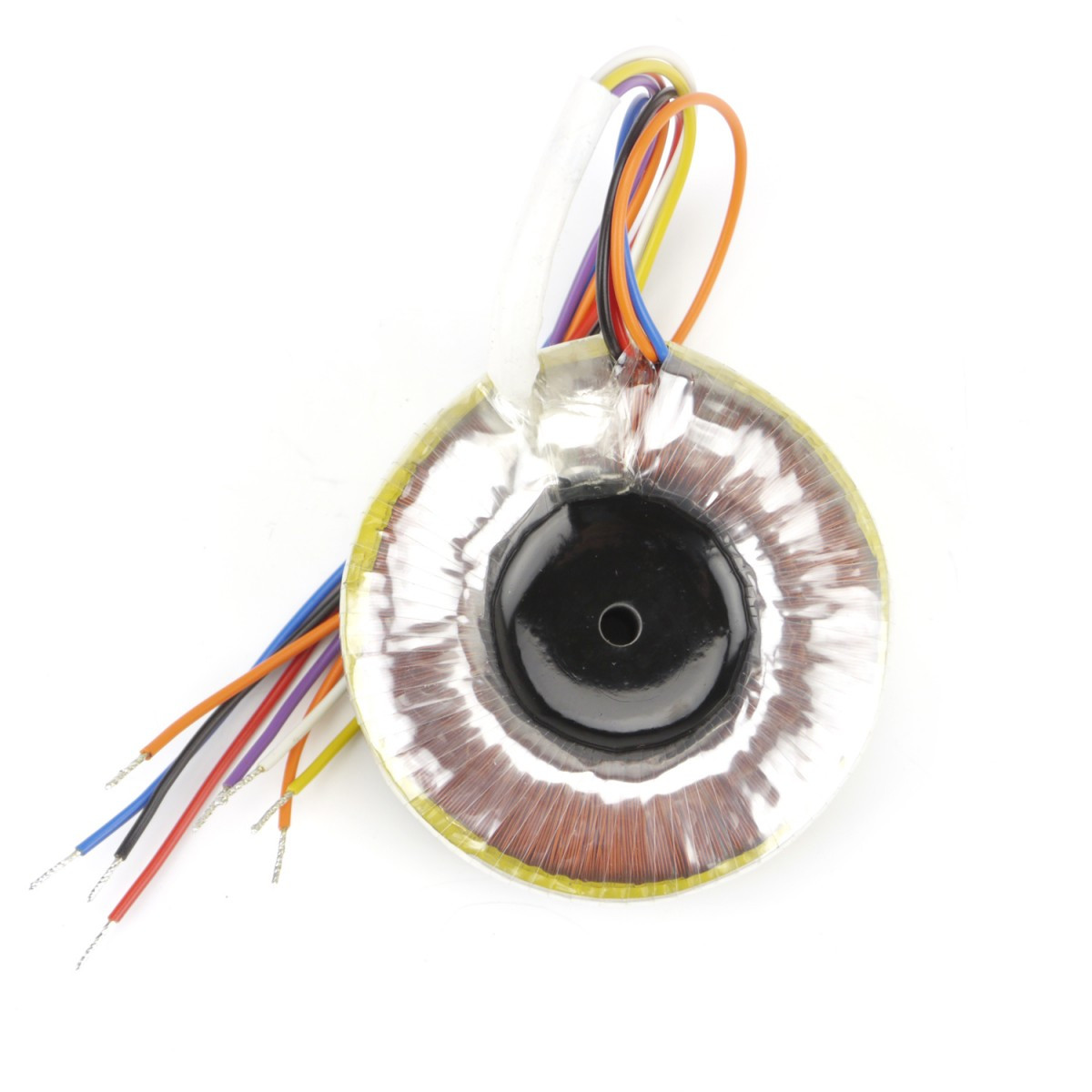
Maybe I did something wrong with the wiring. I connected the white and orange wires on the primary and then purple and yellow wire to the bridge rectifier.

Also - I noticed the transformer and tubes have centre tap for heater current, and so do the tubes. Should I put it to use?

Toroidal-Transformer-Mila-250vct-63vct-48V_b2.jpg
 
OK, looks like you have your transformer wired wrong.  From your description it looks like you have the bridge rectifier connected to the mains. This is very dangerous. DO NOT TURN IT ON AGAIN UNTIL YOU FIX THIS.

Looks like you have the Mila transformer from Don Audio.

The primary has two 115V windings which you need to connect in series. Unfortunately it is not obvious how you do this from the on line documentation so you need to work this out. Disconnect all the primaries. Connect your one side of your  DVM set to read resistance to the yellow wire. Connect the other end to each of the other three in turn (orange, white , lilac). Only one of them should show a DC resistance. This pair is one primary winding , the other pair will be the other primary winding. Let me know the results of this test and we can then work out how to connect them in series.

Next, the bridge rectifier needs to be connected to the secondary HT winding. This is the two brown wires. The red (centre tap) is not needed and should be insulated. The heaters are wired to the heater secondary winding which is the two green wires. Once again, the centre tap is not used and should be insulated.

Take great care, mains voltages can kill you.

Cheers

Ian
 
Sorry, what I meant to say is I connected yellow and purple to the power switch (which is also connected to the mains), and 2 brown ones to the rectifier.  ;D

Only yellow and white had a resistance. So the pairs are yellow/white and orange/lilac.
 

Latest posts

Back
Top