This thread is the official build and support thread for the AMEK/TAC Scorpion I S1000/S1100 and Scorpion II S1001/1101 API 2520 style differential line receiver mod. The Diff.Rev004 is currently (2015/07/16) the latest revision for this little mod. We designed this PCB with help from this incredible forum! Thanks to Mitsos, Gary and a few more for getting me this far!!
Fair Warning!
To install the Diff_Rev00x sub-pcb on your channel-strip you'll need to remove some components from the main board! Removing these components should be done with the utmost care not to damage solder-pads and/or traces! Remember, these consoles we're build half way through the 80's and they came at a budget-price so everything about this console (maybe except the mega-heavy frame) was not built to last for ages! A de-soldering station would be the best option to remove these components from the board!
BOM:
STEP 1: Buy an assembled PCB or build your Diff.Rev00x Kit.
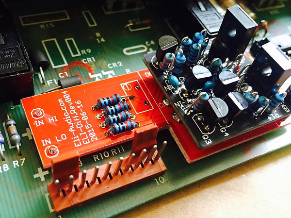
There's only a few components needed for the differential input board as most of them are already on your DOA (Discrete Operational Amplifier). So look at this picture to sort out where to put what. If you're not familiar with CMRR calibration testing don't bother installing a multi-turn trim pot, just extend Rf towards the pots wiper pad. (Yes I thought about this when designing the PCB!) When using 0.1% or matched 1% resistors CMRR (Common Mode Rejection Ratio) will be excellent!
Do not install the header pins to the PCB just yet, as it's far less troublesome to line up the sub-pcb with the main pcb!
Only thing to watch out for is the electrolytic cap polarity, they will go out with a bang if you get it wrong!!
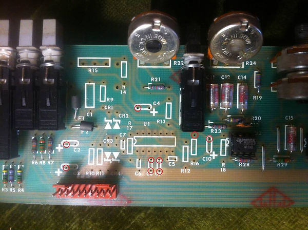
STEP 2: remove these parts from the main-pcb. (red circles represent the sub-connections)

STEP 3: as I said before I prefer to slide the header pins in the main-board first before soldering them to the Diff.Rev00x board. Make sure the holes are clear of any solder residue because you might push the soldering pad away from the board, ending up messing about to get a clean connection! For the Diff.Rev00x boards only seven connections out of nine are needed! There are no pins at the C4 or R16 main board connections.

EDIT:
- To protect your line-source outputs remove R1 and R2 phantom power resitors on the channel-strip PCB!!
- If you want to use both XLR and TRS Line-input connections as a line-source, you'll need to remove and replace R6 and R7 10k resistors with a wire bridge and remove R8 altogether.

Fair Warning!
To install the Diff_Rev00x sub-pcb on your channel-strip you'll need to remove some components from the main board! Removing these components should be done with the utmost care not to damage solder-pads and/or traces! Remember, these consoles we're build half way through the 80's and they came at a budget-price so everything about this console (maybe except the mega-heavy frame) was not built to last for ages! A de-soldering station would be the best option to remove these components from the board!
BOM:
- C1/C2 - 47uF/25V
- C3 - 10p/50V
- R1/R2 - 10R.25/1%
- R3/R4/R5 - 10k.25/1%
- Rf - 10k.25/1% (unless you need CMRR calibration, Rf could be 9.1k with a multi-turn trim pot around 2k)
STEP 1: Buy an assembled PCB or build your Diff.Rev00x Kit.
There's only a few components needed for the differential input board as most of them are already on your DOA (Discrete Operational Amplifier). So look at this picture to sort out where to put what. If you're not familiar with CMRR calibration testing don't bother installing a multi-turn trim pot, just extend Rf towards the pots wiper pad. (Yes I thought about this when designing the PCB!) When using 0.1% or matched 1% resistors CMRR (Common Mode Rejection Ratio) will be excellent!
Do not install the header pins to the PCB just yet, as it's far less troublesome to line up the sub-pcb with the main pcb!
Only thing to watch out for is the electrolytic cap polarity, they will go out with a bang if you get it wrong!!
STEP 2: remove these parts from the main-pcb. (red circles represent the sub-connections)

STEP 3: as I said before I prefer to slide the header pins in the main-board first before soldering them to the Diff.Rev00x board. Make sure the holes are clear of any solder residue because you might push the soldering pad away from the board, ending up messing about to get a clean connection! For the Diff.Rev00x boards only seven connections out of nine are needed! There are no pins at the C4 or R16 main board connections.

EDIT:
- To protect your line-source outputs remove R1 and R2 phantom power resitors on the channel-strip PCB!!
- If you want to use both XLR and TRS Line-input connections as a line-source, you'll need to remove and replace R6 and R7 10k resistors with a wire bridge and remove R8 altogether.


![Electronics Soldering Iron Kit, [Upgraded] Soldering Iron 110V 90W LCD Digital Portable Soldering Kit 180-480℃(356-896℉), Welding Tool with ON/OFF Switch, Auto-sleep, Thermostatic Design](https://m.media-amazon.com/images/I/41gRDnlyfJS._SL500_.jpg)


