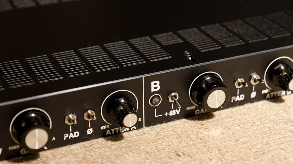
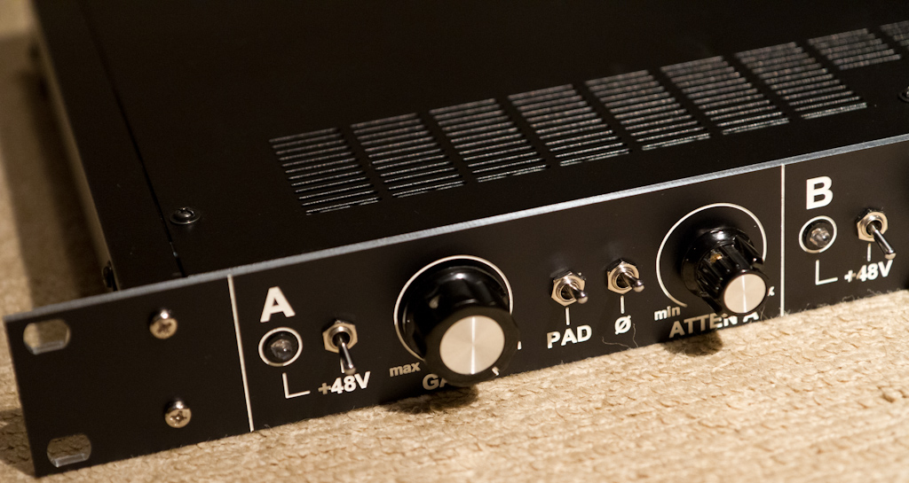
etheory ePreamp001 - 2-stage pre based on Tamas BigFetBloke

GroupDIY Audio Forum

Help Support GroupDIY Audio Forum:

This site may earn a commission from merchant affiliate links, including eBay, Amazon, and others.

etheory

Well-known member
Joined
Mar 21, 2011
Messages
604
Location
Sydney, Australia
Hi there!

I've been working on a project for a friend recently that's come far enough to share.
I was asked to build them "2-channels in a box" of a versatile pre-amplifier for recording microphone and keyboards.

Price was quite a big factor, as was portability, so it had to be simple and cheap, but still have all the fancy features.

After far far too long designing (it was an excellent exercise in learning - doing a lot of my own research, and finally purchasing the full version of EaglePCB to do the work), I came up with the first design exercise for my company "evolutionary recordings" - called for the moment the ePreamp001 (for lack of a better name).

It has a 20dB input pad switch, +48V phantom, output phase reverse, a 2-stage amp with 20-70dB of variable gain and an output attenuator.
It uses the ClassicAPI 2622 input and 2623-4 output transformers.

I chose the 2623-4 mostly for it's extremely competitive price and PCB mounting ability.

I used the Tamas BigFetBloke DOA's for their extremely low cost, simple design, ability to drive a load and insane power 8) - cost was so tight here that even a 2520 or 2510 would have driven the cost up too much.

This was also my first "complex" PCB manufacturing exercise - where I decided that using a vendor to do the boards was my best bet for speed and even price (I can no longer afford 4-6hrs of manually-adjusted CNC'ing of boards - my time is worth more than that). The resulting boards worked out so well, and look and feel so amazing that I know I'll be using a professional supplier every time now - it's almost cheaper to even prototype on professional PCB's they are so cheap these days....

So having read loads of posts here, I took bits and pieces of everything I could find, simulated everything I could think of in LTSpice like a million times in a million different configurations and made something that I feel very nicely addresses the original needs of my friend.

I just realized looking at these images that I maybe shouldn't have printed ClassicAPI on the board - this is NOT a ClassicAPI product, it just uses the Ed Anderson transformers - and maybe I should have written Ed Anderson on there instead - oh well - hindsight hey.... THANKS ED!!!!

So, here we go with the photos.... (please excuse the poor quality - the 7D wasn't in the house when I took these - so they were just taken on my phone).

First here are the PCB's from the CNC of the BigFetBlokes (which was the process that made me realise not to CNC again - since I messed it up and had to fix stuff by soldering to the legs of other components - fun....):
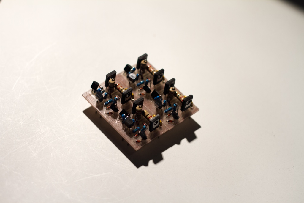
MG_9047_thumb.jpg


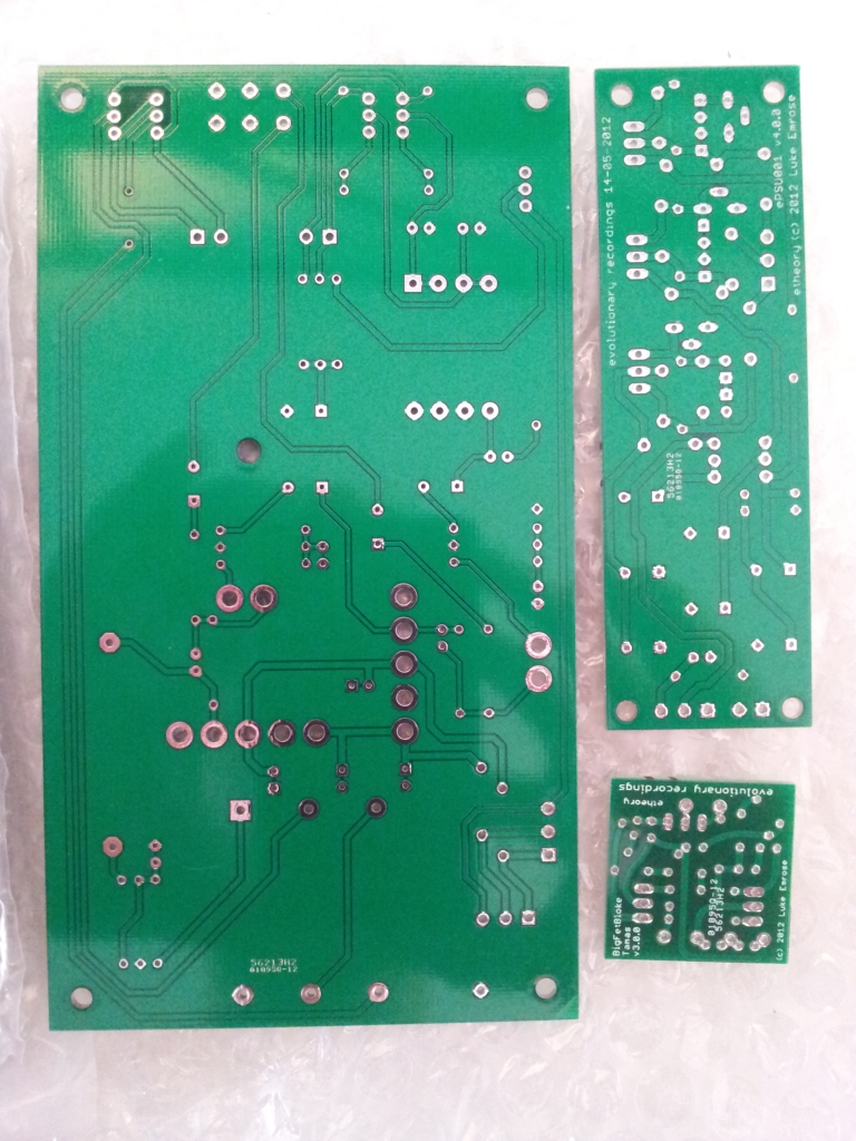
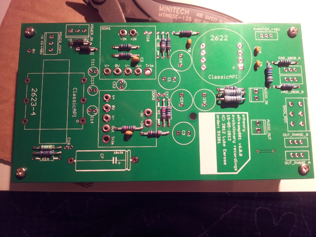
Next were the PCBs for the PSU and Preamp:
Top:
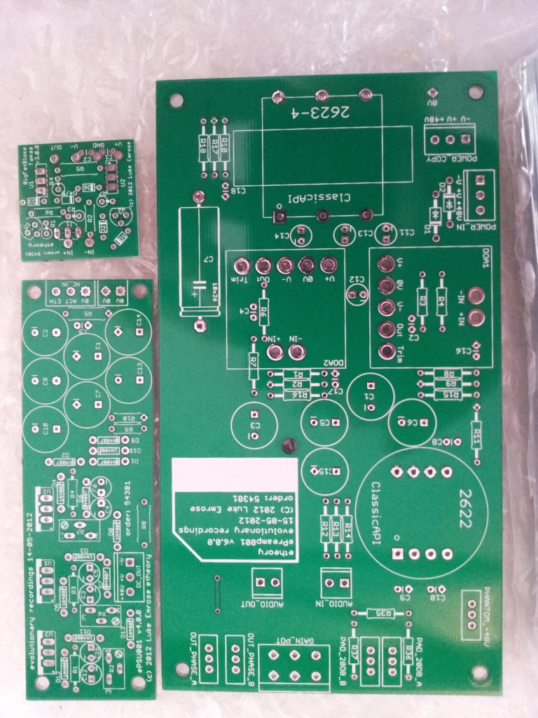
2012-07-25-12.12.38_small.jpg


Bottom:
2012-07-25-12.13.22_small.jpg


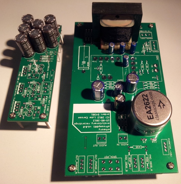
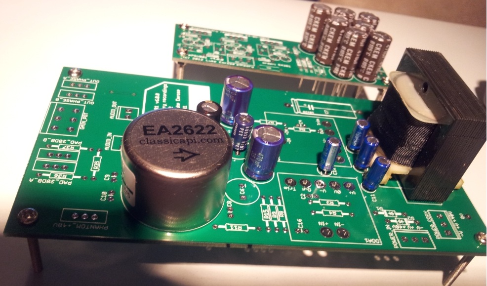
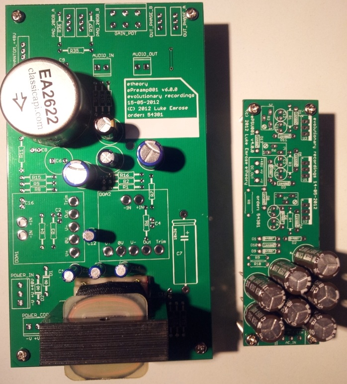
Then I did a parts test with my fingers crossed, since I had never used the EaglePCB footprints I'd made for the 2622 and 2623-4 - but as they say - measure 100 times - get someone else with more precise tools to cut once - and BOOM, everything fit perfectly:
2012-07-25-22.39.20_small.jpg
2012-07-25-22.39.37_small.jpg
2012-07-25-22.40.15_small.jpg
2012-07-26-01.05.53_small.jpg


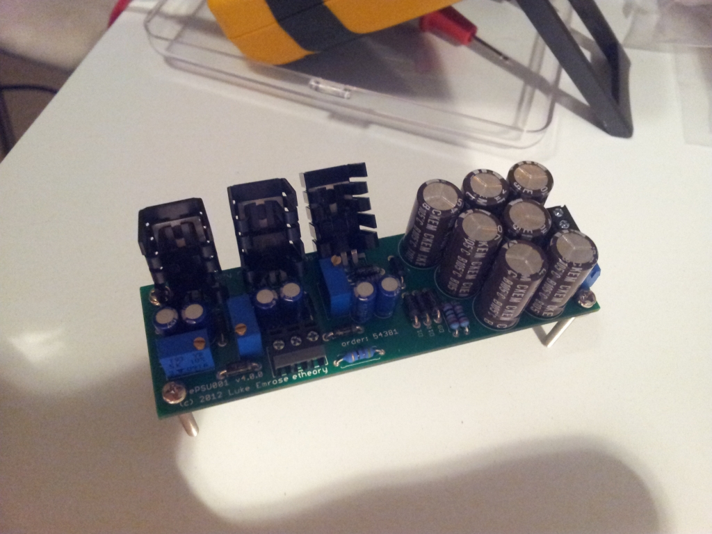
First I assembled the PSU - which worked perfectly straight off the bat (note to self, buy heatsinks that face the opposite direction 8)):
2012-07-28-00.48.43_small.jpg


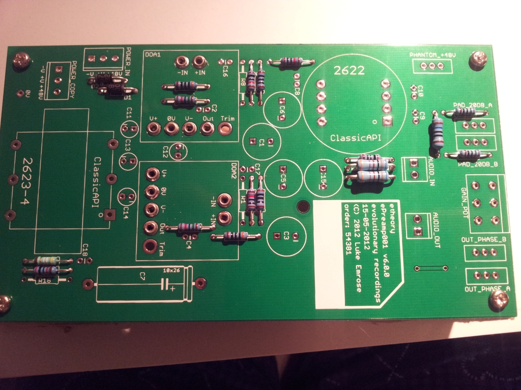
Then the preamp boards themselves - starting with the resistors:
2012-07-28-02.24.14_small.jpg


Then the small caps:
2012-07-28-02.59.46_small.jpg


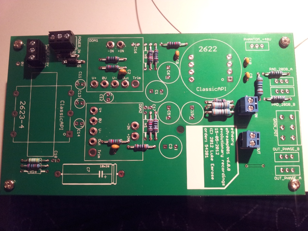
Then terminals:
2012-07-28-03.06.40_small.jpg


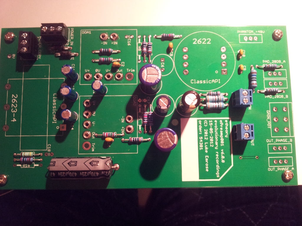
Then the big caps:
2012-07-28-03.20.40_small.jpg


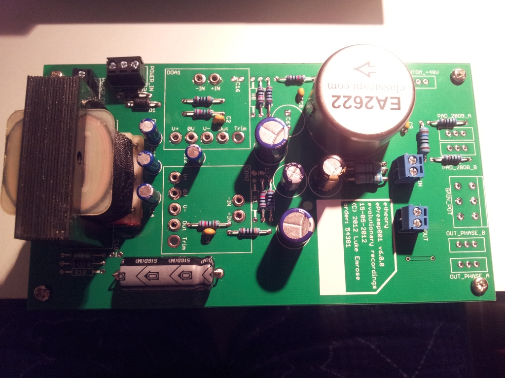
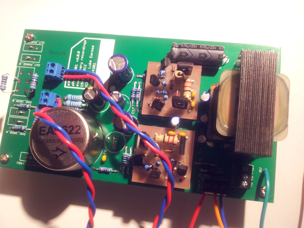
Then the transformers:
2012-07-28-04.10.06_small.jpg


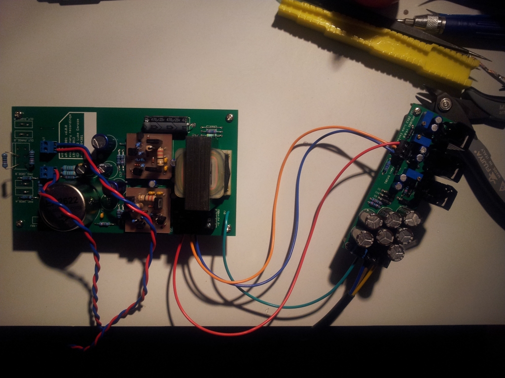
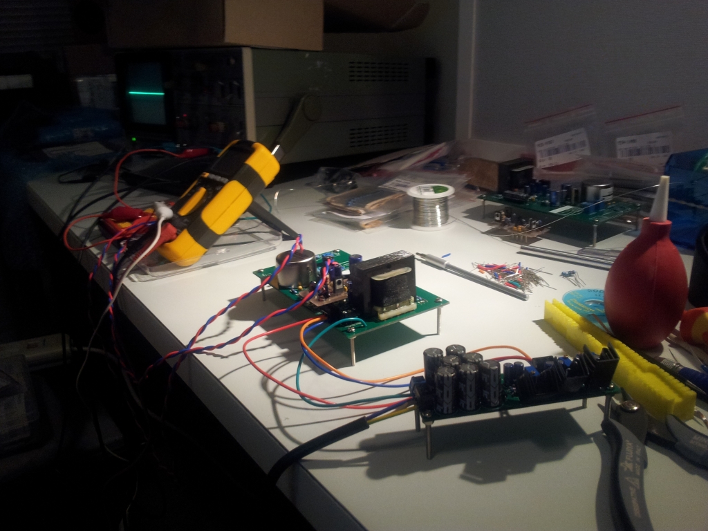
Then it was testing time:
2012-07-28-05.37.41_small.jpg
2012-07-28-05.38.17_small.jpg
2012-07-28-05.38.29_small.jpg


And I am happy to report everything works just fine straight away.

There are a few things left to go, like me forgetting to buy the correct feedback and zobel caps, and then substituting with wildly incorrect values that produce a little ringing after the input transformer (1000pF instead of 220pF in the zobel with the 10K resistor, but easily fixed).

Next up I will test with all the switches and pots in place - this test was done by substituting the external parts with wire links for the switches and a 10K resistor for the pots.

Fingers crossed - I might actually have a successful preamp design here!

I couldn't be happier!

More news soon - I need about two weeks to get the rest of my organization together to finish it off and put it in a case etc. - then it goes to it's new owner for some recording!
 
Will you possibly be offering these in the future if successful? I got 2 of those 2623-4 transformers laying around, and cheap sounds very good :) Wouldnt mind some more color in the preamp arsenal.
 
I have quite a few spare PSU/Preamp/BigFetBloke PCB's since minimum order was 10 for each, and my client only needs 1PSU/2Preamp/0BigFetBloke(I already had CNC ones).

I'll keep a couple of each for myself, but yeah, absolutely, there will be some spares - if people would be interested in buying them, then totally, that would be great.

What's the best way to do that? Should I contact Ethan and do a white market thing, or for "surplus" like this is it different?
I've tried reading the guidelines before and got a little bit lost as I've never had to sell anything on here before.

In the future I guess I probably will open up a White Market listing for my company - as it ramps up - since I also have other bits and pieces in the pipeline - such as an API2510 "clone" in 2520 format that Joe Neil at Doppler Studios has been testing for me for a couple of weeks, and so far the results seem pretty amazing in comparison to a bunch of 2520 clones - so - no doubt people might show some interest in those too eventually.

Cheers for the interest - it's very encouraging that people are interested! I'll have a definite answer for you in a couple of weeks once I built it and verify that it's a kosher product!
 
I've posted the Eagle footprints I made here for the Ed Anderson 2622 input and 2623-4 output for anyone who is interested in adding these to their own projects - these footprints seem to work perfectly (i.e. they have been tested as above) and give a nice amount of copper to solder to and have correct hole-sizes, text and outlines: http://www.evolutionarytheory.com/downloads/Eagle/ClassicAPI.lbr
 
Well, I was doing this to learn, and learn I am!
First thing I noticed is that this Power Supply sucks - it doesn't cut the mustard at all.

I thought I could get away with 17VAC 1A plug pack powering +-24VDC 600mA but there is NO WAY that is happening ;-)
Lesson learned!

It will now be repurposed to power my +-15VDC low current test circuits for my DIY synthesizer modules - a much much easier load for it - and a nice use for the plugpack.

The preamps are definitely preamping though, and the mic signal is coming through, it just sounds terrible due to the PSU completely unable to deliver the required power, and generating a PSU rail that looks like waves on the ocean.

I've gone back to the simulator and simulated end-to-end including the power supply and now the issues are extremely clear.

The low-efficiency linear half-wave rectification can't handle it, not to mention I DEFINITELY need a 25VAC transformer with centre tap to power this, at I think 50VAC to be nice and safe, to replace this wall-wart fail I thought I could get away with.

Still, I'm learning a lot, and at the end of it, this thing will still be amazing 8)

Also, another thing I learned is not to poke a 1x oscilloscope probe into a feedback loop of a high-gain opamp to see what's happening - BOOM oscillation - obviously. It's one of those things that you read about and until you do it, scratch your head and go OOOOHHHHH! you wonder what the heck has happened.

Anyway, more soon after a revised PSU....
 
OK, so I just revised everything.
I've dropped the rails to +-15V to give the PSU enough room to breathe and reliably provide power.

I've swapped out the BigFetBlokes for an API2510 in the first stage (which in my particular design has VERY VERY little current draw) followed by an API2520 of my own design, which in both cases massively reduces the current requirements of the circuit, and therefore allows the existing wall-wart based PSU to function without issue (or extra cost, aside from my infinite personal time cost....).

So now I have an amp not quite as I originally envisaged, however, it's now operating really nicely, noise free, in the way originally intended, from a microphone source, even on the test-bench, so hopefully all cased up it'll be even better.

Here is the front panel graphic I am hoping to cut out this Saturday, then put everything in the box and BOOM - it'll be my first fully finished custom project.

I've learnt a LOT along the way. The most important lesson being, NEVER EVER try and spec your PSU close to what the simulator says it needs - give it at least twice that, cause in the real world stuff sucks more juice.

I also learnt to never probe with a 1x probe around high-gain feedback paths, it has to be at least 10x, else the low impedance is just too much, and the observer ends up becoming the observed.

You all knew this no doubt, and so should have I, but sometimes doing is much better than discussing ;-)

More soon, but I've almost wrapped this one up - very excited to do my next project now ;-)
 

Attachments

  • front_panel_v02_02_converted.jpg
    front_panel_v02_02_converted.jpg
    58.5 KB
OK, after an epic 15hrs or so with my first time using a CNC to do front panels, I can say two things.

1.) They work really well for making perfect sized holes.
2.) They don't work well for fine engraving when you don't entirely know what you are doing ;-)

Wiring these up tonight hopefully....


Attachments

  • 20120826_124520_converted.jpg
    20120826_124520_converted.jpg
    252.1 KB
IT'S PARTIALLY ALIVE!

Here is a test recording done with it (excuse the clipping of my AD's, after so long wiring this thing up, I just simply couldn't be bothered recording this test again, but there are a few seconds of perfection in there too....).

Again, I had to ditch the BigFetBloke DOA's for this particular implementation due to a lack of juice to drive them. However, the 2510 and 2520 with the wall-wart is actually working perfectly.

This is just my test SM58 running through this little puppy:
http://dl.dropbox.com/u/10030435/etheory/abc123/For%20Chris%20Gresh/Test%20Recording%2001.wav

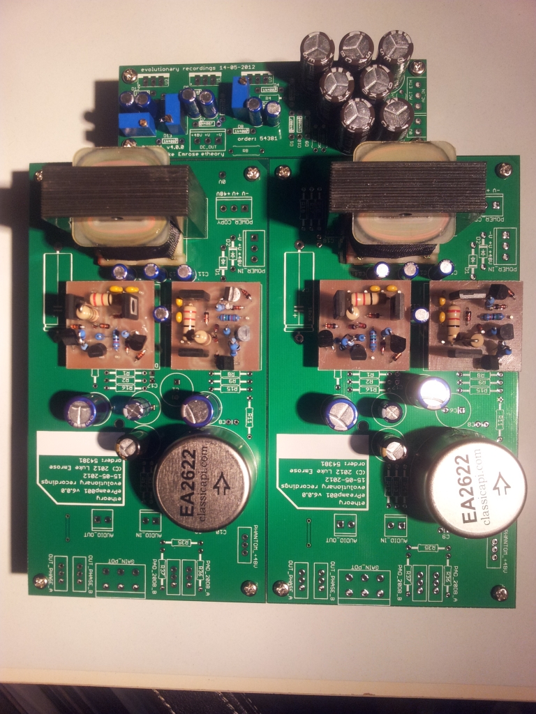
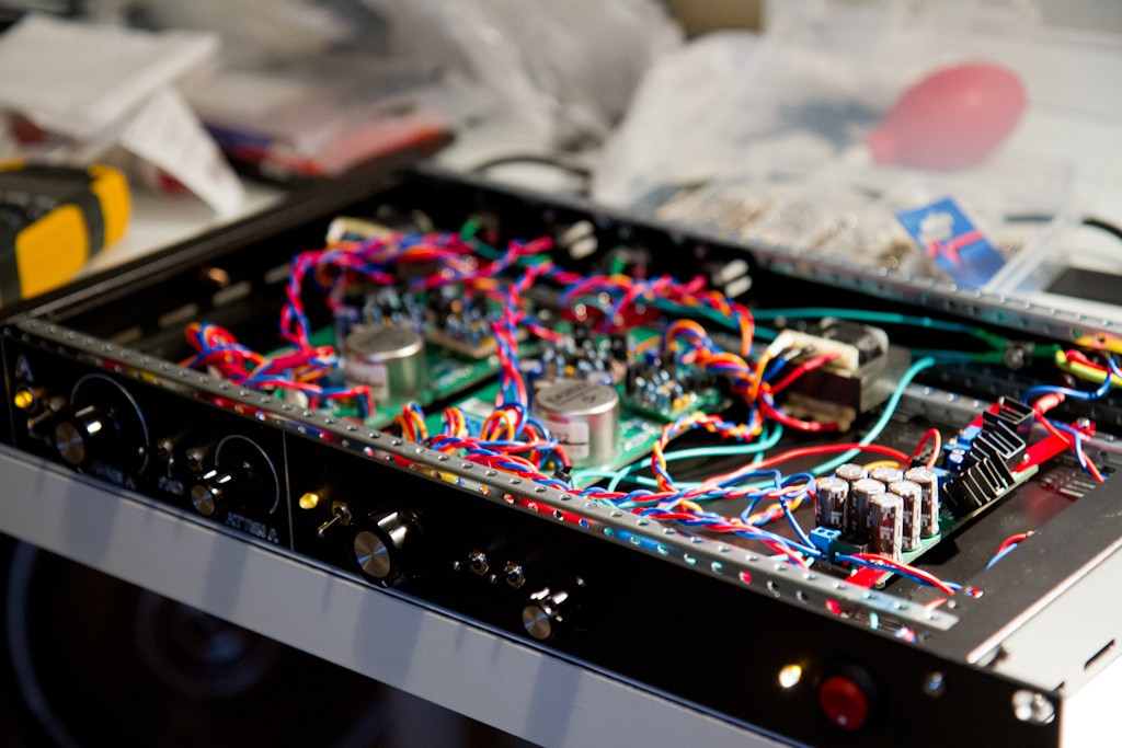
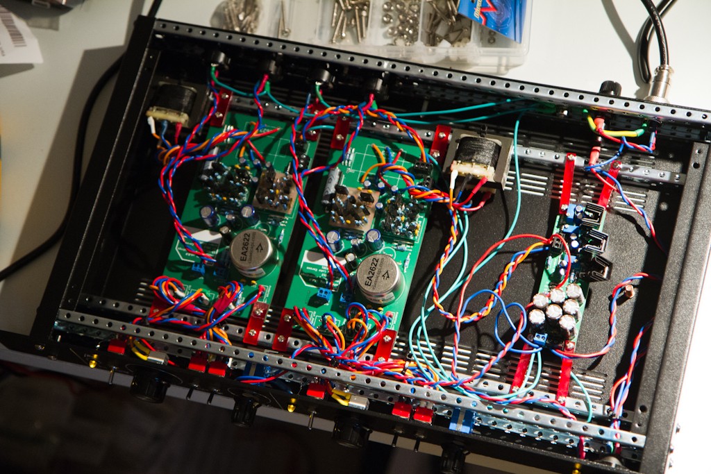
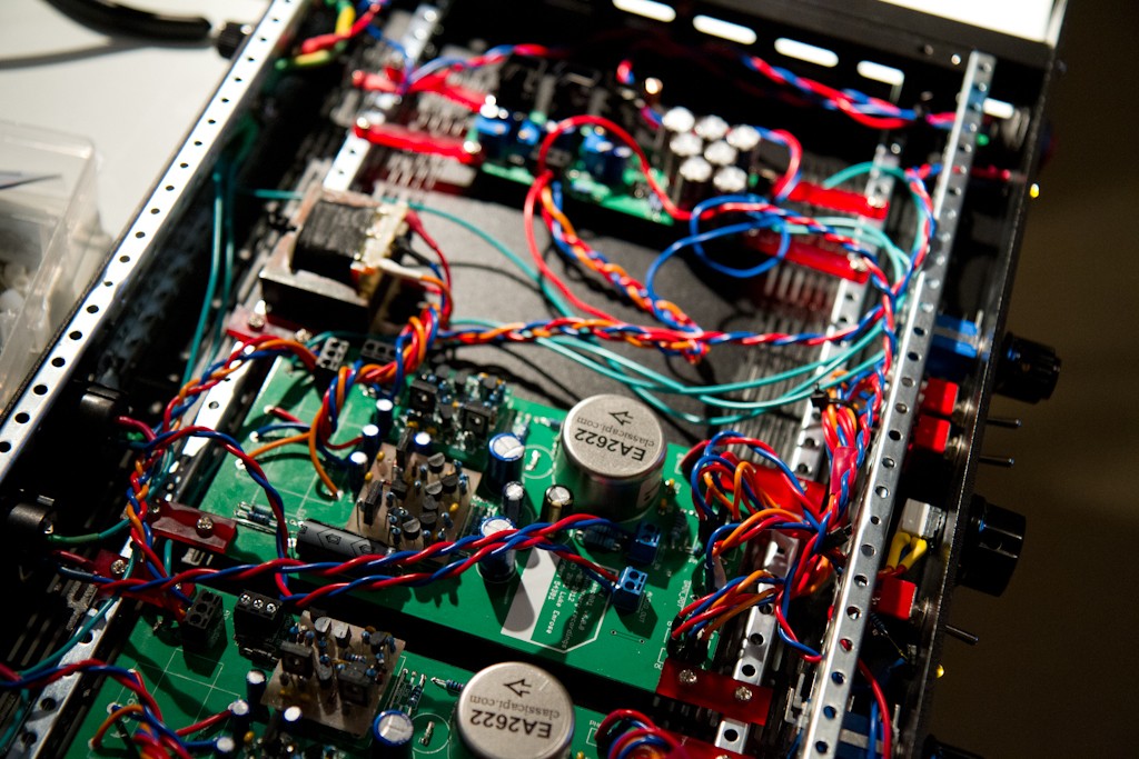
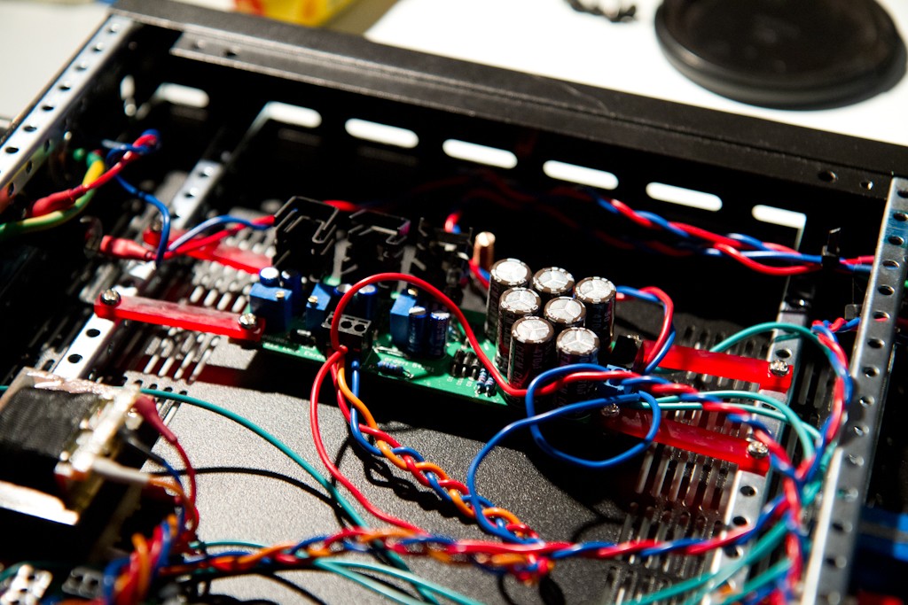
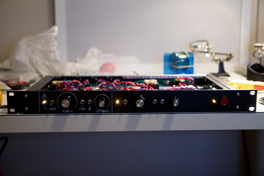
And here is an image of the belly of the beast.

The left channel is "completely wired" and the right is about 70% done.

The sound is clear, precise, and VERY VERY quiet. The noise floor and hum are quieter than the residual noise in this room of my computer fan with the mic on the other side of the room and facing the other direction, so all in all I'm VERY VERY happy with how it sounds.

More soon....

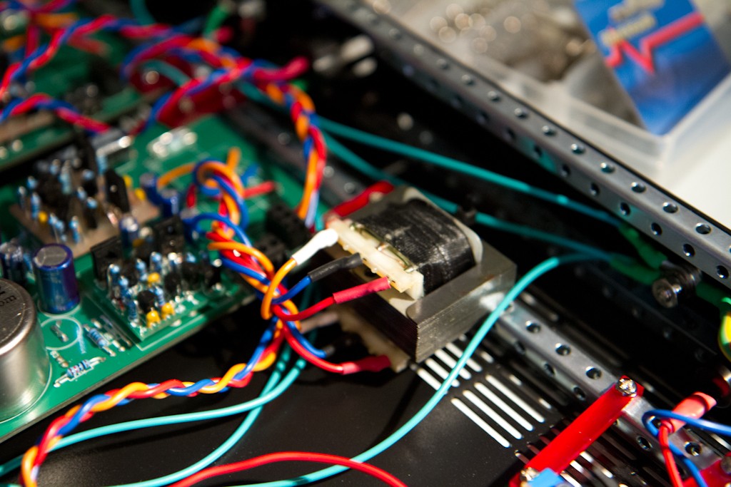
P.S. I found that it wouldn't fit in 1u with the transformer on the PCB (facepalm....) so I had to go off board unfortunately.... Note to anyone else if they ever want boards to be careful with this simple gotchya....


Attachments

  • 2012-09-02 17.07.44_converted.jpg
    2012-09-02 17.07.44_converted.jpg
    595.6 KB
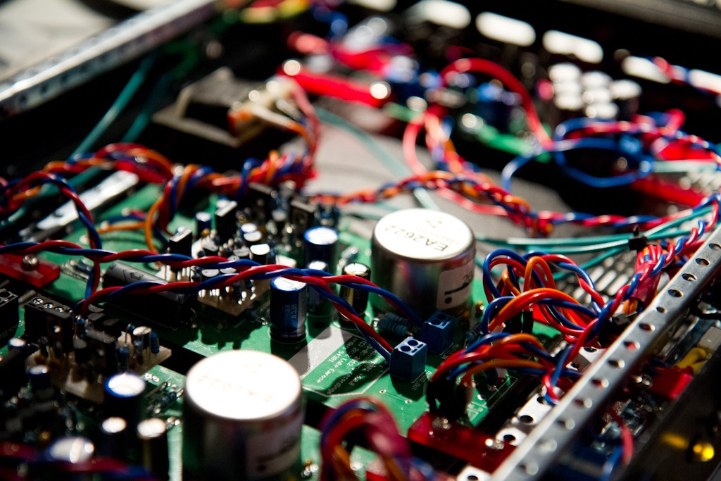
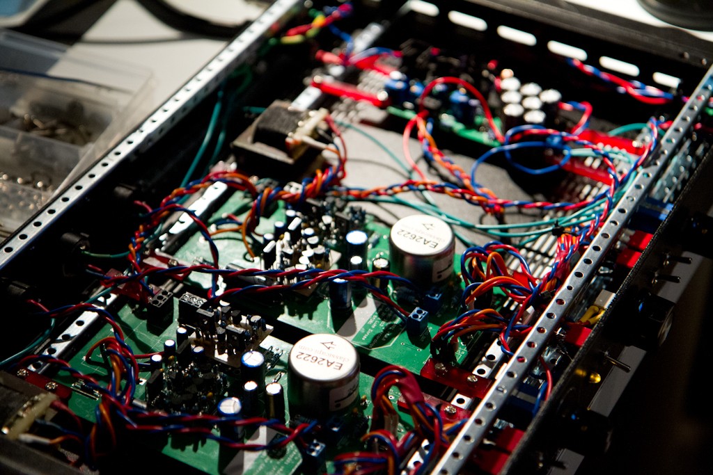
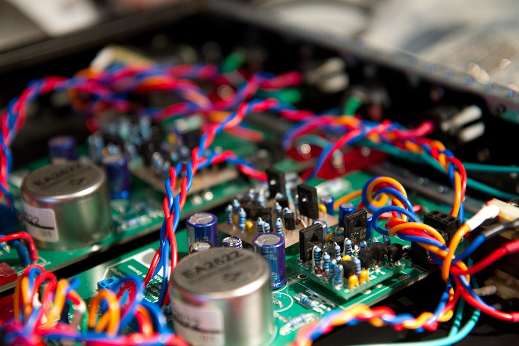
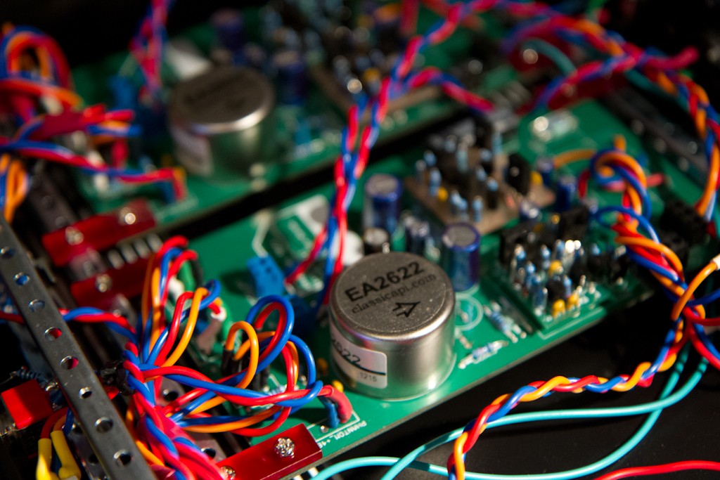
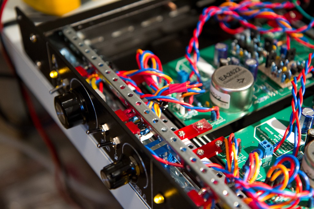
It's very much alive now - I just got back from laser cutting some mounting brackets for the PCBs.
Here are some shots:

MG_9536_converted.jpg

MG_9539_converted.jpg

MG_9540_converted.jpg

MG_9541_converted.jpg

MG_9542_converted.jpg

MG_9544_converted.jpg

MG_9545_converted.jpg

MG_9546_converted.jpg

MG_9547_converted.jpg

MG_9548_converted.jpg

MG_9550_converted.jpg

MG_9551_converted.jpg

MG_9552_converted.jpg

MG_9556_converted.jpg

MG_9557_converted.jpg


I'm pretty happy with the esoteric laser-cut plastic mounting bars (my first ever use of the laser cutter for cutting!) and the whole thing is working well.
All that remains now is to wire up the output attenuators, wait on the replacement front panel for the this one that I butchered in the CNC (oops....) and boom, it's be off to the lucky guy who ordered it (though I'd love to keep it, it sounds great).

Anyway, almost there, will post some audio when I get the chance to put it through it's paces again.

cheers.

P.S. it's been a very productive day today, and, in an entirely unrelated note, I just composed this piece for piano:
http://soundcloud.com/evolutionarytheory/evolutionary-theory-song-for-1
 
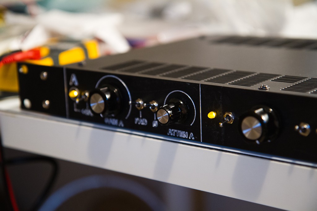
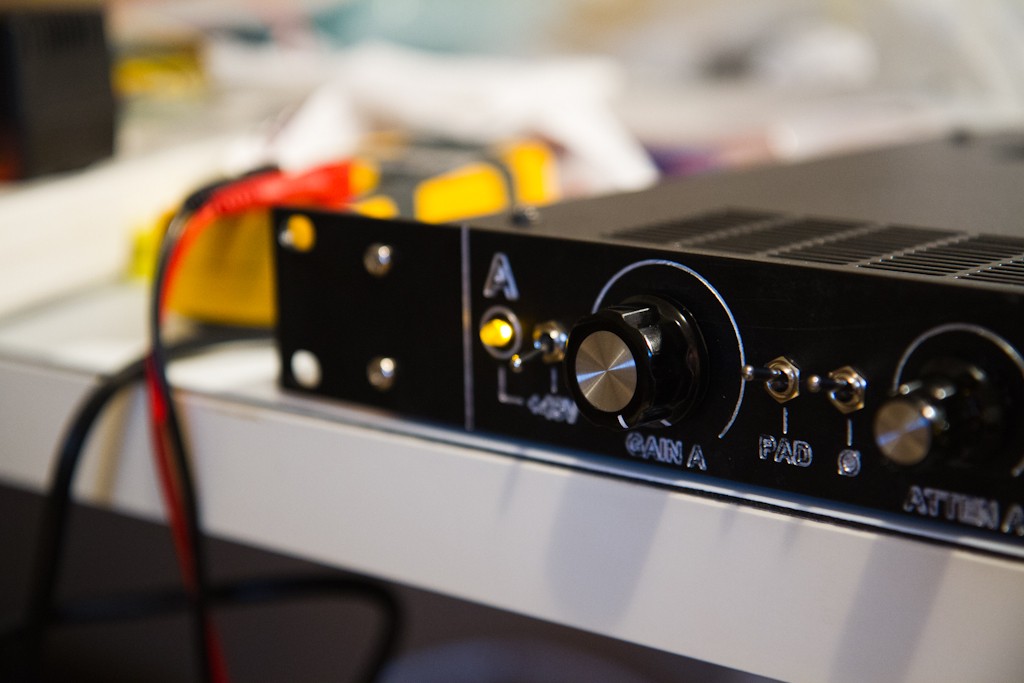
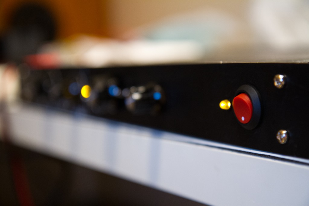
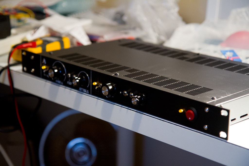
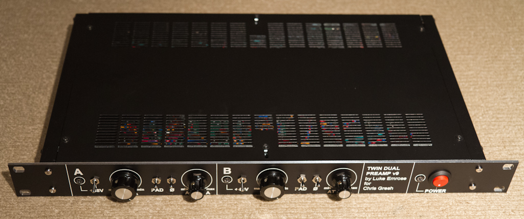
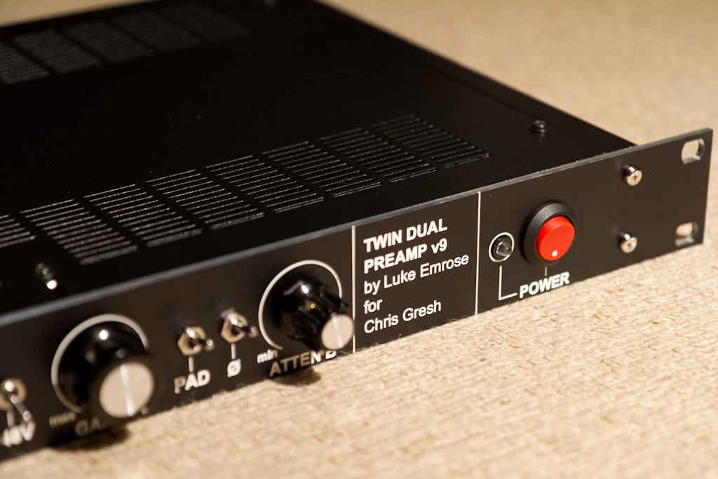
OK, so, FINALLY, here is the fully completed test version I made for a friend of mine (who, absolutely loves how it sounds by the way).
It's now fully tested, finally.

Thanks also to Joe Neil for your fantastic assistance with the 2510 and 2520 DOA's I ended up designing/creating for this (the BigFetBloke was just too power hungry for the on-board PSU). Your measurements were very useful to let me know that it really does compare extremely well to the very best out there.

Very happy with this, my first ever totally 110% custom build.

Also thanks to Frank for the front panel. Really love your service.
Except I must have really made a pile of errors on the file I gave you, since I managed to get every single hole too small, and ended up just filing them all out a little more, but it's all good now - you'd never know.

Enjoy the photos, more about board availability soon as I sort out my inventory and figure out how many boards I have:

MG_0019.jpg

MG_0020.jpg

MG_0021.jpg

MG_0022.jpg

MG_0024.jpg
 
Ptownkid said:
Congrats man!

As for selling your extras, i can't imagine you'd have to have a white market listing just to sell off some leftovers...

Thanks Ptownkid! And thanks for the heads up too.
It's such a nice feeling to finish a project, especially now that I ACTUALLY have some spare time again to do this stuff with now that the album I was working on is finally finished.
 
etheory said:
I've learnt a LOT along the way. The most important lesson being, NEVER EVER try and spec your PSU close to what the simulator says it needs - give it at least twice that, cause in the real world stuff sucks more juice.

I also learnt to never probe with a 1x probe around high-gain feedback paths, it has to be at least 10x, else the low impedance is just too much, and the observer ends up becoming the observed.

You all knew this no doubt, and so should have I, but sometimes doing is much better than discussing ;-)

Hi,

congratulations for your project, i respect your effort in this short time.
Do you have any particular reason for simulating psu when it is pretty simple circuit? Wall power is difficult to predict, some (often lower cost) transformers too. I have similar low V tx situation with tap for heater regulator, i'm using schottkys with ldo for lower drops. Fortunately it has enough I tp get away with this combination.
What was the result of using 1x probe for high gain feedback paths? Oscillations?
 
My3gger said:
Hi,

congratulations for your project, i respect your effort in this short time.
Do you have any particular reason for simulating psu when it is pretty simple circuit? Wall power is difficult to predict, some (often lower cost) transformers too. I have similar low V tx situation with tap for heater regulator, i'm using schottkys with ldo for lower drops. Fortunately it has enough I tp get away with this combination.
What was the result of using 1x probe for high gain feedback paths? Oscillations?

Thanks!

Whilst the PSU is simple, the way it interacts with the rest of the circuit was not.
A few things I didn't except were observed both in the simulator and in reality.
The first was that putting a passive resistor and cap network before the regulators is very sensitive to super-low-frequency oscillation.
The simulation found this and the reality proved it, so I'm glad I got rid of that idea early.

I had a lot of data about the transformer so I decided to simulate it, including the input AC, and see what effects my filtering choices were likely to have.
So through that, I found that I had to completely change the entire design to fit within PSU spec.
The Tamas BigFetBlokes drew way too much current for the PSU at +-24V, whereas at +-15V the 2510+2520 stage drew a lot less and were stable.

Yes, probing with 1x produced a combination of oscillations and made the opamps occasionally lock up after a period of oscillation, and also produced DC offsets through the circuit starting at the opamps. I think this is due to the lower impedance test point, producing a low impedance path to ground at the wrong places.
 
I know this is an old topic, but just a quick FYI.

I revisited this after my original failure with the BigFetBlokes drawing too much current at +-15V and found the rather obvious issue.

I once read on the original Tamas BigFetBloke thread to make the current-setting resistor, which replaces the 1.1mA regulating diode originally specced as a 1N5298 (D7 on schematic), 15K or 18K.
Which is what I originally tried.
Unfortunately this makes the stand-by power about 1W, which put my original power supply under too much strain to sustain clean power.

After some quick simulation, I found setting D7 to a 24K or 25K resistor puts 1.1-1.3mA though the current source Q3, making everything run nicely from +-15V rails.

For +-24V rails, I'd recommend around 42K.

This drastically reduces PSU requirements with no effect on measured sound/frequency response/distortion etc. etc.

The amp still runs class A with this biasing and retains the original beautiful sound.
Q4 consumes around 210mW and Q5 around 100mW, and you can drive 600R with ease.

enjoy!
 
Really impressive work Luke! I like your style - lots of details, and the determination to make a first class product against all odds.  Thanks for sharing, especially your findings on running the BFB at lower current.  I'm building some now based on Laurent's layout, and that info will come in handy.
 

Latest posts

Back
Top