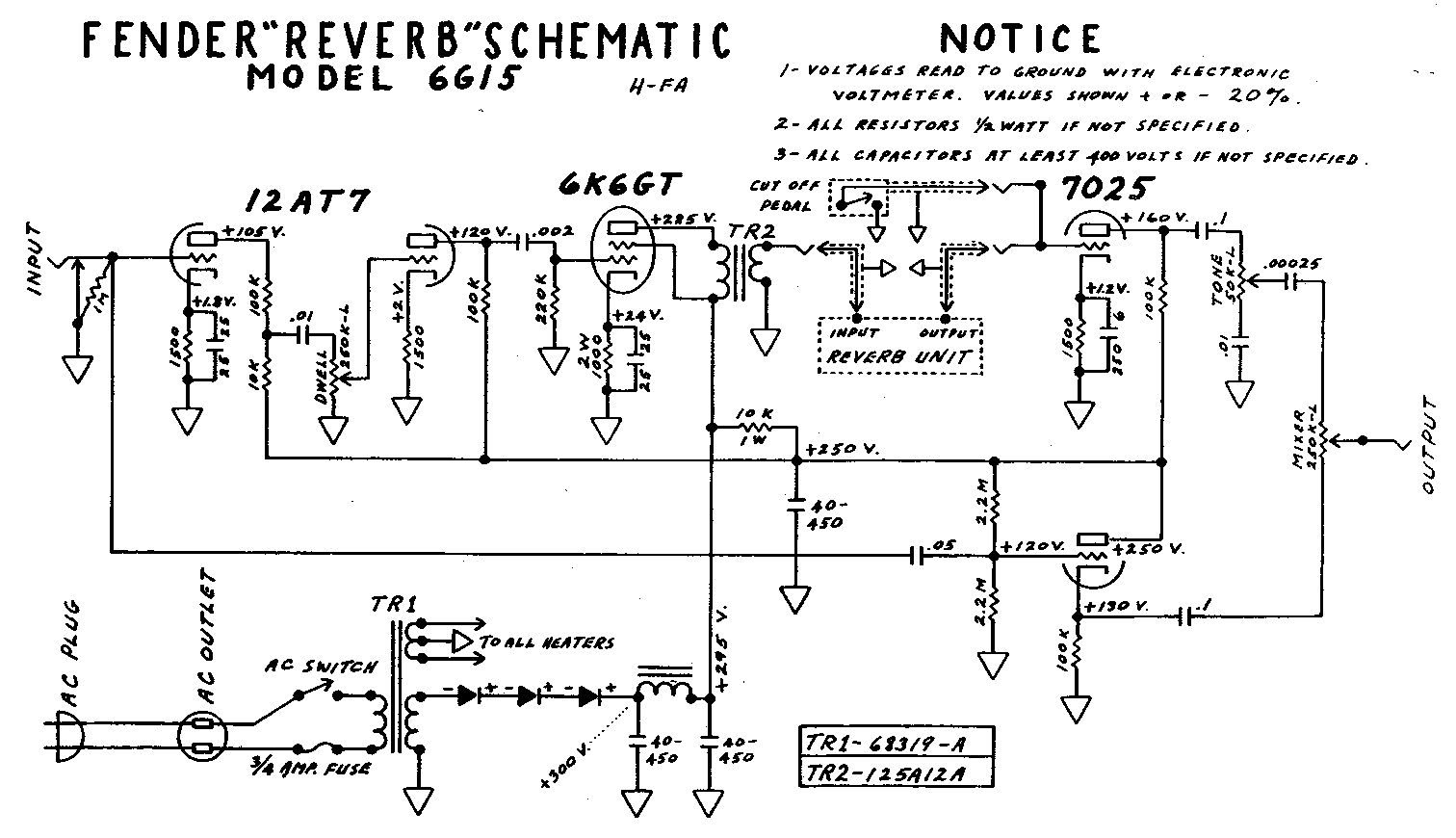
Fender Reverb 6G15 Knockoff

GroupDIY Audio Forum

Help Support GroupDIY Audio Forum:

This site may earn a commission from merchant affiliate links, including eBay, Amazon, and others.
now if you space out like i did and forget to order the little reverb pan bag thingy,

then just take a break and think up something, like a matching tolex reverb bag made from the leftovers, how pimped out is that with the gold hardware added to the handle, bling bling all the way,


no need for a heavy duty sewing machine or stink glue, just use all those holes they punched in the pan for bolts, you get a tighter fit, which means the bag won't dampen the springs like they can sometimes do when they are old and gray, jus sayin...
 

Attachments

  • reverb3.jpg
    reverb3.jpg
    221 KB · Views: 77
here is the pan loaded in the back,

that big block of wood supports the spring brackets, and  is bolted to the handle on top so the handle does not pull thru the 1/4 inch ply, nuthin worse than a broken handle letting the box roll down the stairs,

there are multiple hookup points for the springs in case they stretch a bit, and i soldered them to the brackets so the ends don't open up.


Attachments

  • reverb4.jpg
    reverb4.jpg
    212.4 KB · Views: 96
the chassis is ready to stuff, we are using a current production Vibro Champ output as a reverb driver, a 12 henry choke, and a multi can cap because they sound better,  ;D

Mallory, do they still make those or is that a rip out of an HP voltmeter?

that sucker has to be dried out, i'll give it a week, :-X

the RCA cables are hard wired on the amp end for reliability,
 

Attachments

  • reverb5.jpg
    reverb5.jpg
    110.7 KB · Views: 83
ok the chassis is bolted in, that is the 6X4 rect on the left with a little spring clip doo dad as a retainer,

i thought that Fender bolted the pwr trans on the inside of the chassis to keep hum out of the reverb pan, but i think the main reason was that it hits the pan if it is mounted on the back, i lucked out and had enuff clearance, clarance,

i added a ground wire to each phone jack which gets soldered to the chassis with the big iron on his hip, these units can be noisy, so added filtering and better grounding helped keep this thing quiet, even with the AC heaters,

the wood circuit board was clear coated since it is a high Z circuit,
 

Attachments

  • reverb8.jpg
    reverb8.jpg
    208.8 KB · Views: 116
used a starbucks large coffee lid to trace out the raduis,

plenty of images on the web of the 6G15 for bootlegging specs,


Attachments

  • reverb9.jpg
    reverb9.jpg
    156 KB · Views: 71
got grill cloth?

if CBS wants to get pissy about plastic, then we will just make it a Vox Reverb Unit, what say?


im a gonna spray the chassis plate white and add white knobs with gold trim,

the knobs are a three pack of Strat knobs drilled out for 1/4 inch,

they have Volume, Tone and Tone lettered  on them which will match up nicely with Mix Dwell and tone so one last pic tomorrow.
 

Attachments

  • reverb10.jpg
    reverb10.jpg
    218 KB · Views: 86
CJ said:
Fairchild iron on the way, so cool your jets,  :D

nuthin as cool  like a juicy reverb, if you never played this unit, then just listen to a dick dale album or something,

1/4 inch plywood for the ultimate in cheapness and it is easy to hack and drill so wtf, over?

6 by 18 22 ga from Lowes for 5.99 because we would rather spend money on drugs,

Acutronics pan for 23 bucks, looks lioke they sold the farm to China, Beltron to be exact, which means we will need to:

1) shim up the loose transducer coils to prevent mechanical loss,
2) put a dab of jb weld at the junction of the springs to prevent mechanical loss
3) hard wire the connectors that feed the transducers for less signal loss,
4) bolt the pan directly to the baffle board so we can save more money on the silly springs that always break, besides, the pan sounds better bolted down to the baffle board, who takes road trips at 5 bucks a gallon and pay to play? screw that, this tank ain't goin nowhere,

ok, bend the chassis with 2 pieces of angle iron clamped on both sides then pound away with a hammer,punch some socket holes and we are on our way,

Interesting information as I built a revibe.
http://www.el34world.com/Hoffman/images/revibeschematicToreT.gif
When I read your post I opened it up and had a look at my pan.
It's made in the usa, and has 
1. loose transducercoils, how did you shim those up ? with paper ?
2. each transmissionspring is made of two separate springs, connected in the middle with a rivet, is that ok or do you suggest epoxying them together ?
3. connections with transducers are plugged, I'm gonna solder those.
4. do you mean how the whole pan is hung in the cabinet ?
    I'm confused since in the pictures you post you do hang it with springs ?

I was wondering too if a B-pan (open-side-down) can be converted to a C (connectors up) ?
The explanation here seems to suggest a C is the better pan, but I'm not sure.
http://www.amplifiedparts.com/tech_corner/spring_reverb_tanks_explained_and_compared

Also, my reverb-mix-pot is doing almost everything in the first quarter ?
 
Hey CJ, or any other kind soul..... I am working on one of these reverb units also and have a question. It looks like the screen grid will be at a higher voltage than the plate on the 6k6gt tube. Is this correct? I thought that the screen was normally at a lower voltage than the plate. Maybe I am just missing something ???


Thanks in advance....

gP5EZ.gif
 
ward said:
1. loose transducercoils, how did you shim those up ? with paper ?
I was wondering about this myself...

ward said:
2. each transmissionspring is made of two separate springs, connected in the middle with a rivet, is that ok or do you suggest epoxying them together ?
If the rivet seems like it allows some play between the springs, then that would lead to some mechanical loss, which can be lessened by providing the most rigid connection possible.

ward said:
3. connections with transducers are plugged, I'm gonna solder those.
That's probably a good idea. Half the time someone brings an amp into my shop complaining about a lack of reverb, it's a simple matter of one of those craptastic RCA connectors coming loose.

Edit: Reading further down the page to which you linked, it appears that you guys are referring to something like a Molex connector inside the pan. Sounds unnecessary...

ward said:
4. do you mean how the whole pan is hung in the cabinet ?
    I'm confused since in the pictures you post you do hang it with springs ?
I would leave the tank with the intended spring suspension, unless, like CJ, you prefer the sound of the mechanical feedback mentioned on the page to which you linked. We're simulating room acoustics here, so all of this is pretty subjective.

ward said:
I was wondering too if a B-pan (open-side-down) can be converted to a C (connectors up) ?
The explanation here seems to suggest a C is the better pan, but I'm not sure.
http://www.amplifiedparts.com/tech_corner/spring_reverb_tanks_explained_and_compared
I guess that would depend on whether it's really necessary. I would imagine the different mounting positions take this into account, otherwise I'm not sure what the reason would be for the factory to offer different units for specific mounting positions. You can verify this by opening your tank and checking to see if the magnets are mounted with the long side vertical when the tank is horizontal. If that's not the case and they're just using the same mountings, then I guess you'd have to change whatever it is that they do to the horizontal mount units to whatever it is they do to the vertical mounts, because there's gotta be something different about them.

ward said:
Also, my reverb-mix-pot is doing almost everything in the first quarter ?
You mentioned that you built this yourself; is it possible that you installed a linear pot instead of a log pot? If it is log, did you know that not all "audio" pots share the same curve? Some people get really anal about this...

I do know that when I swapped out the 6V6 for the original tube, a 6K6, in my Fender Reverb reissue, I found that some of the pots gained way more usable range of travel. I think it was "Mix" and "Tone". The circuit's definitely designed for a 6K6.

dspruill said:
It looks like the screen grid will be at a higher voltage than the plate on the 6k6gt tube. Is this correct? I thought that the screen was normally at a lower voltage than the plate. Maybe I am just missing something ???
The screen is normally at a lower voltage than the plate. In this case, they are held at the same potential. At least, I don't think the trip through the inductor formed by the transformer primary drops an appreciable amount of voltage (I may be wrong). I always thought of this as running the beam tetrode like a triode, but again, I might be wrong.
 
Ego Tripper said:
I was wondering about this myself...
I made some wooden mini wedges by sanding veneer down. 

Ego Tripper said:
If the rivet seems like it allows some play between the springs, then that would lead to some mechanical loss, which can be lessened by providing the most rigid connection possible.
I did put a blob of epoxy on each connection.
The tube amp doctor reverb pans do it with a blob of solder.
They also have hardwired connections from rca to transducer.
So I removed the molex connector.
I tried a 4AB... pan from tube amp doctor and it brings me much closer to what I'm looking for.
The 9... pan is way too long and 'washing' out all resolution and attack.

Ego Tripper said:
I would leave the tank with the intended spring suspension, unless, like CJ, you prefer the sound of the mechanical feedback mentioned on the page to which you linked. We're simulating room acoustics here, so all of this is pretty subjective.
You're right, I guess I have to answer my own question by listening to it.


Ego Tripper said:
You mentioned that you built this yourself; is it possible that you installed a linear pot instead of a log pot? If it is log, did you know that not all "audio" pots share the same curve? Some people get really anal about this...
I replaced my 500k pot with a linear 250k and I have some improvement,  I'm gonna try with the 250k bypassed with a 35k resistor.
Ego Tripper said:
I do know that when I swapped out the 6V6 for the original tube, a 6K6, in my Fender Reverb reissue, I found that some of the pots gained way more usable range of travel. I think it was "Mix" and "Tone". The circuit's definitely designed for a 6K6.
I have a 6K6.

Ego Tripper said:
The screen is normally at a lower voltage than the plate. In this case, they are held at the same potential. At least, I don't think the trip through the inductor formed by the transformer primary drops an appreciable amount of voltage (I may be wrong). I always thought of this as running the beam tetrode like a triode, but again, I might be wrong.
According to the schematic the voltage on the grid 295V is dropped through the transformer to 225V.
I believe the schematic is right.
 
Screen lower than plate in cathode biased amps is the new thing, higher is the old thing.  I recall higher screen helps long term stability, attracts more stray electrons out of the vacuum. 
 
ward said:
According to the schematic the voltage on the grid 295V is dropped through the transformer to 225V.
I believe the schematic is right.
That's what I get for referring to the windowed schematic in the thread and being too lazy to scroll (although, in my defense, I'm temporarily stuck using a mouse without a scroll wheel/ball).

ward, you mentioned using a 250k lin pot. Have you tried using 250k log? This is one of those subjective areas where you're probably not going to use the second half of the linear pot's travel ('cause then the wet signal would be louder than the dry signal). A log pot might be more useful as you'll get finer control over the area you're likely to use.

Interesting to hear about the washed out quality of the 3-spring tank... I've always wondered about those.
 
the output transformer dcr is fairly so it does drop the plate below the screen, depending on which xfmr you use,

dcr on a vibro champ output is about 300 ohms if you use that to drive the pan,

supposedly the stand alone reverb unit xfmr is 30 to 1,

a vibro champ output is a 44:1, and the regular twin reverb type xfmr is 50 to 1.

yes the tank is held by four springs in the cabinet, then there are 4 more springs inside the pan itself, then 4 more actual reverb springs that make the delay, so 12 springs , no wonder it sounds springy,

i think the horizontal vs vertical might also have to do with the travel lock thingy on the stand alone, but not sure,


we had some EI 75 around, which is a size larger than the stock reverb output, so we have a 1.5 stack wound pri-sec-pri,, could have gone pri-sec-pri-sec-pri for 100 k hz response but no need since the reverb springs and mini transformer will not need this good of response,

i do not know if the new transformer improved the sound, but it is matched up with the 6k6 a lot better with  no core saturation which means less heat, 10 x 10 stacking for stable air gap,

this is the same lam used in the Neve output,

new core bracket needed, so DIY,


Attachments

  • reverbxfmr.jpg
    reverbxfmr.jpg
    205.6 KB · Views: 38
there was no room on the back of the chassis so i hung it off the side, seems like less hum with the new transformer and location,

i wonder what a speaker would sound like if wired up to the 6k6 output?


Attachments

  • reverboutput1.jpg
    reverboutput1.jpg
    287.9 KB · Views: 61

Latest posts

Back
Top