Folks,
Since we released the digital controlled front end, some people have been asking about integrating a 4 switch front end into the 1176 design.
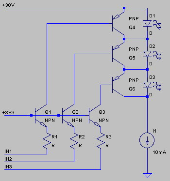
Having looked at the 1176, it looks like there's a +30V supply, and a -10V supply.
The MSP430's that we use run from a maximum 3.3V supply. As such, some circuitry on the board needs to bring down the 30V, to a more sensible 3.3V.
This thread is about the power supply. I'll start a thread regarding the switch in the future.
So, here are the options I've chewed on to solve this power supply problem.
The easiest is one great big linear regulator, however, dropping 26.7V accross it, at 40mA max (4 LED's, each driving 10mA) will generate 1.06W of heat. In a T0220 package (large) this will increase the temp by 20C or so. In a smaller TO-92 package (that's used for my LP2950-3.3 regulator) it'll increase the temperature by 150C!
Using a switch mode supply would be the most environmentally friendly way of doing it. However, most Pro Audio folks I know don't want SMPS's in their system, if they can avoid it, and it adds significant complexity and difficult to source components (and maybe some SMT work too!)
So the conclusion I came to was to use a series resistor in front of the LP2950-3.3 to dissipate some of the power.
I've created a small excel file that I used to calculate the value of the series resistor. It can be found here: http://www.tendolla.com/designgallery/main.php/v/tools/Power+dissipation+in+regulators+with+series+resistors.xls.html
I make no guarantees for it's accuracy.
My current requirements will be between 10mA (one LED on) and 40mA (all LED's on).
by toying with the resistor value in the second window, at maximum current draw (40mA), my LP2950-3.3 will increase in temperature by 35C if I use a 470Ohm series resistor. My resistor will need to dissipate 0.95W. (within the 1W spec)
Any holes in my theory here? My ego won't be hurt - I promise")
Since we released the digital controlled front end, some people have been asking about integrating a 4 switch front end into the 1176 design.
Having looked at the 1176, it looks like there's a +30V supply, and a -10V supply.
The MSP430's that we use run from a maximum 3.3V supply. As such, some circuitry on the board needs to bring down the 30V, to a more sensible 3.3V.
This thread is about the power supply. I'll start a thread regarding the switch in the future.
So, here are the options I've chewed on to solve this power supply problem.
- One big linear regulator, that takes 30V and brings it all the way down to 3.3V
- A power resistor in series with the regulator, so that some of hte power is dissipated in teh resistor
- A small switch mode power supply circuit
The easiest is one great big linear regulator, however, dropping 26.7V accross it, at 40mA max (4 LED's, each driving 10mA) will generate 1.06W of heat. In a T0220 package (large) this will increase the temp by 20C or so. In a smaller TO-92 package (that's used for my LP2950-3.3 regulator) it'll increase the temperature by 150C!
Using a switch mode supply would be the most environmentally friendly way of doing it. However, most Pro Audio folks I know don't want SMPS's in their system, if they can avoid it, and it adds significant complexity and difficult to source components (and maybe some SMT work too!)
So the conclusion I came to was to use a series resistor in front of the LP2950-3.3 to dissipate some of the power.
I've created a small excel file that I used to calculate the value of the series resistor. It can be found here: http://www.tendolla.com/designgallery/main.php/v/tools/Power+dissipation+in+regulators+with+series+resistors.xls.html
I make no guarantees for it's accuracy.
My current requirements will be between 10mA (one LED on) and 40mA (all LED's on).
by toying with the resistor value in the second window, at maximum current draw (40mA), my LP2950-3.3 will increase in temperature by 35C if I use a 470Ohm series resistor. My resistor will need to dissipate 0.95W. (within the 1W spec)
Any holes in my theory here? My ego won't be hurt - I promise