NOT AVAILABLE ANYMORE!
I've done my own PCB layout of the circuit for the TG1 Zener Limiter (original schematics somewhere in this thread Anyone interested to build a TG1 clone ?) and while I usually etch my own boards I've decided this time to try a fabrication service.
It was the first time I used such a service and the boards came out surprisingly well. I had to order a few more than I really needed, so why not offer them here?!
One limiter PCB is 35 Euros plus shipping. I'm also offering my bipolar PSU board for 10 Euros each. If you're interested in either the Limiter and/or PSU boards, email me - make sure to include your Groupdiy name and your country.
Please no PMs!
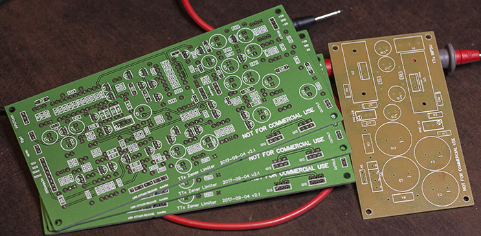
To buyers I will provide a BOM, schematic and wiring diagram because my part numbering is different from the original, found in the thread I mentioned before. Stuffing the board is easy but as a lot of wiring is involved, this is not a project for beginners.
Here's a link to the guide which includes the schematic, BOM, wiring instructions, PSU info, etc.
https://www.dropbox.com/s/9kkpxcxr0hebzp0/TTx Zener TG Guide.zip?dl=0
If you find errors or things that are missing from the guide please let me know.
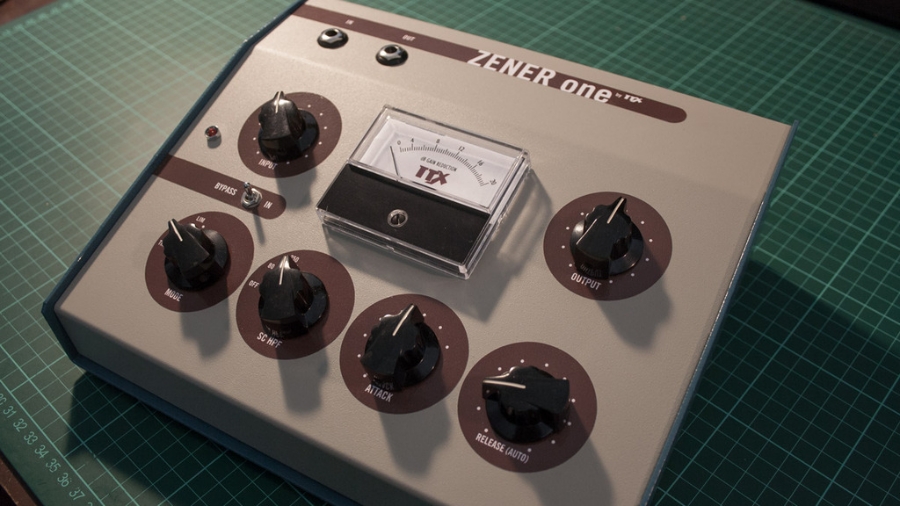
I've built two units using three of my boards that are in use at my studio. All I can say is it's an awesome sounding compressor/tone box/saturation device. My version has a switchable sidechain hipass filter, the sidechain can be switched out for THD mode and there are options for an auto release and a sidechain link between two boards.
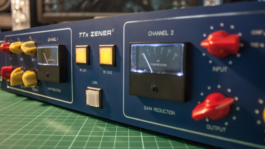
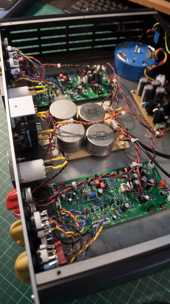
My boards are not exactly true to the original schematic. At first I had to come up with a new way to bypass the unit which included that the compressor stage is now non-inverting as opposed to the inverting original. My version of the bypass is not a hard bypass. The signal still goes through the input transformer, the output stage and output transformer which adds to the versatility as a coloured tone box. The 'bypassed' signal is at unity gain (with a 2:1 IPT) for easy A/B testing.
There's also a small difference in the input stage.
The most significant difference is in the output stage which runs unnecessarily hot in its original form. I have built both the original and my version and I couldn't spot a difference in sound, just a lot less heat and current consumption. Drive capability is about the same nevertheless. No heatsinks required anymore, but there's enough space around the output transistors for mounting heatsinks if you want.
Last but not least the GR meter circuit in my version is adjustable and much more precise with 1 mA meters, which are a lot easier to get (and cheaper) than 'Ernest Turner 2.4 mA'.
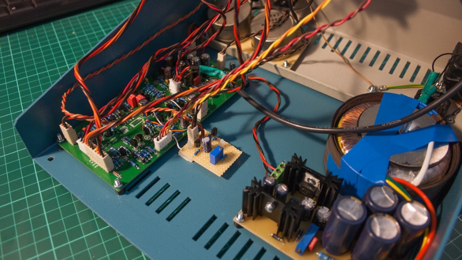
sorry for the messy wiring
In my builts I'm using Haufe transformers for input (step-down 2:1) and output (ratio 1:1) but you're free to use anything you desire or even electronically balance the signal. However, I would recommend a 2:1 or even 4:1 input transformer because the threshold is very sensitive, although I've raised it a bit by about 6 dB. The original is un-balanced in/out and it can be used this way as well. The boards can be stuffed with just off-the-shelf components, the output transistors are the ubiquitous BD139/140 (with optional pads for mounting MJE3055/2955 instead), the rest of the transistors are BC550C/549 559C.
When stuffing, I would strongly recommend to socket a few key components (mainly resistors) to be able to try different values. With this design it's certainly not an easy task to get two boards respond exactly the same. When I built my stereo version I was surprised how well-behaved the compression action tracks between two channels (even with link OFF) but after switching out the sidechain of both (THD mode), the distortion reacted completely different. I was able to adjust this by changing one or two resistors. The board's pads are of good enough quality to take a few solder/un-solder cycles, if you're careful. As I said before, it's not a project for beginners and you must be willing to experiment a little. But isn't it that what DIY is all about!?
A good and low noise +/- 28 volts PSU is needed. I have used self-etched boards with my own layout for this. All the infos for the PSU I'm using are included in the guide. As an alternative to self-etching I'm also offering this PSU board as a ready-made PCB which can also be used for other projects that need a bipolar power supply. See above.
I've done my own PCB layout of the circuit for the TG1 Zener Limiter (original schematics somewhere in this thread Anyone interested to build a TG1 clone ?) and while I usually etch my own boards I've decided this time to try a fabrication service.
It was the first time I used such a service and the boards came out surprisingly well. I had to order a few more than I really needed, so why not offer them here?!
Please no PMs!

Here's a link to the guide which includes the schematic, BOM, wiring instructions, PSU info, etc.
https://www.dropbox.com/s/9kkpxcxr0hebzp0/TTx Zener TG Guide.zip?dl=0
If you find errors or things that are missing from the guide please let me know.
I've built two units using three of my boards that are in use at my studio. All I can say is it's an awesome sounding compressor/tone box/saturation device. My version has a switchable sidechain hipass filter, the sidechain can be switched out for THD mode and there are options for an auto release and a sidechain link between two boards.


My boards are not exactly true to the original schematic. At first I had to come up with a new way to bypass the unit which included that the compressor stage is now non-inverting as opposed to the inverting original. My version of the bypass is not a hard bypass. The signal still goes through the input transformer, the output stage and output transformer which adds to the versatility as a coloured tone box. The 'bypassed' signal is at unity gain (with a 2:1 IPT) for easy A/B testing.
There's also a small difference in the input stage.
The most significant difference is in the output stage which runs unnecessarily hot in its original form. I have built both the original and my version and I couldn't spot a difference in sound, just a lot less heat and current consumption. Drive capability is about the same nevertheless. No heatsinks required anymore, but there's enough space around the output transistors for mounting heatsinks if you want.
Last but not least the GR meter circuit in my version is adjustable and much more precise with 1 mA meters, which are a lot easier to get (and cheaper) than 'Ernest Turner 2.4 mA'.

sorry for the messy wiring
In my builts I'm using Haufe transformers for input (step-down 2:1) and output (ratio 1:1) but you're free to use anything you desire or even electronically balance the signal. However, I would recommend a 2:1 or even 4:1 input transformer because the threshold is very sensitive, although I've raised it a bit by about 6 dB. The original is un-balanced in/out and it can be used this way as well. The boards can be stuffed with just off-the-shelf components, the output transistors are the ubiquitous BD139/140 (with optional pads for mounting MJE3055/2955 instead), the rest of the transistors are BC550C/
When stuffing, I would strongly recommend to socket a few key components (mainly resistors) to be able to try different values. With this design it's certainly not an easy task to get two boards respond exactly the same. When I built my stereo version I was surprised how well-behaved the compression action tracks between two channels (even with link OFF) but after switching out the sidechain of both (THD mode), the distortion reacted completely different. I was able to adjust this by changing one or two resistors. The board's pads are of good enough quality to take a few solder/un-solder cycles, if you're careful. As I said before, it's not a project for beginners and you must be willing to experiment a little. But isn't it that what DIY is all about!?
A good and low noise +/- 28 volts PSU is needed. I have used self-etched boards with my own layout for this. All the infos for the PSU I'm using are included in the guide. As an alternative to self-etching I'm also offering this PSU board as a ready-made PCB which can also be used for other projects that need a bipolar power supply. See above.

Last edited:


![Electronics Soldering Iron Kit, [Upgraded] Soldering Iron 110V 90W LCD Digital Portable Soldering Kit 180-480℃(356-896℉), Welding Tool with ON/OFF Switch, Auto-sleep, Thermostatic Design](https://m.media-amazon.com/images/I/41gRDnlyfJS._SL500_.jpg)


