Gain pot in an inverting op amp stage, DC issue

GroupDIY Audio Forum

Help Support GroupDIY Audio Forum:

This site may earn a commission from merchant affiliate links, including eBay, Amazon, and others.

saint gillis

Well-known member
Joined
Nov 4, 2012
Messages
911
Location
Brussels - Belgium
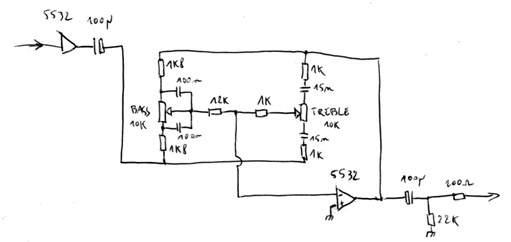
  Hello, I want to make a Baxandall Bass & Treble EQ, something quite similar to this :
baxandall-tone-control-circuit.gif

  In his book, D.Self says there's should be no DC flowing through the pots if we use TL07X, but that we should add DC blocking capacitors if we use NE553X ...  I guess DC can't flow through the treble pot anyway... But it can flow through the bass pot..
  Where to implement these DC blocking caps in such a circuit?
 
There does need to be a dc path from the output pin of the op amp to its non-inverting input else there will be no bias. But this should not be done via the EQ pots.

You are right, the treble circuit is already dc blocked. To achieve the same with the bass you could connect the right hand 10K to the other side of the 4.7uF.

Cheers

Ian
 
ruffrecords said:
You are right, the treble circuit is already dc blocked. To achieve the same with the bass you could connect the right hand 10K to the other side of the 4.7uF.

Cheers

Ian

I dont think so,  DC feedback to the inverting input is indeed done via the bass control pot, putting the 10k resistor at the left of the 4.7uF cap would interrupt DC feedback. It is not as simple as it sounds.  If you dont want to use TL072, perhaps use something like OPA2134?, I agree that the 553x would be the better choice thou.
 
JohnRoberts said:
add a cap in series with the bass pot wiper "and" add a high impedance feedback resistor from op amp output to - input.

JR

Thanks, so something like 22µ? would you put it between the wiper and the 10K or between the 10K and the - input ?
A high impedance feedback resistor, like 1Meg for a NE5532 ?
 
user 37518 said:
I dont think so,  DC feedback to the inverting input is indeed done via the bass control pot,
Which is poor design practice which is why I pointed out there does need to be a dc feedback to the non- inverting input but NOT via the EQ.

Cheers

Ian
 
saint gillis said:
Thanks, so something like 22µ? would you put it between the wiper and the 10K or between the 10K and the - input ?
The way I wrote it should suggest at the wiper, but with two passive components in series like that the order of them does not matter to the electrons.

The cap can add a LF pole so consider the -3dB point formed by cap and say 20k so I expect 22uF is OK. I would be tempted to put that cap at the pot wiper instead of - input so there is less opportunity for noise pickup.
A high impedance feedback resistor, like 1Meg for a NE5532 ?
High enough to not degrade the max boost (100k), so 1M seems fair.  The bias current of a 553x will create a DC voltage drop at the output. The NPN input transistors will have a bias current flowing into the input LTP bases so the voltage drop across your 1M will be positive.  Which suggests to me you might want to reverse the polarity of the output 4.7uF DC blocking cap to be consistent with the expected DC operating point.

JR
 
Thank you JR, great information!

JohnRoberts said:
I would be tempted to put that cap at the pot wiper instead of - input so there is less opportunity for noise pickup.
Why is that?

JohnRoberts said:
The bias current of a 553x will create a DC voltage drop at the output. The NPN input transistors will have a bias current flowing into the input LTP bases so the voltage drop across your 1M will be positive.  Which suggests to me you might want to reverse the polarity of the output 4.7uF DC blocking cap to be consistent with the expected DC operating point.
Sure I just picked up this schematic online because I was too lazy to draw mine...
 
If you're using an NE5532 for noise performance reasons you might want to test to see if you can actually detect a measurable difference in performance. Specifically, can you see a change in the noise floor at max bass boost with TL07X vs NE553X? With only 20dB boost I don't think you will. It's vaguely possible. I don't know. JFET input op amps do have higher noise at low frequencies. But I still doubt you will see a difference.

If you really want to be pedantic about this, then just use a low-offset bipolar like LM4562 (now called LME49710?) which is "ultra" low noise and low offset (unless maybe the source Z is huge). Yeah it costs $2.50 instead of $0.80 but do you really care?

Personally I would much rather spend money on low-offset op amps just so that I can dodge large caps in the signal path. In fact, you should consider ditching the input and/or output caps depending on what those nets are attached to.
 
squarewave said:
If you really want to be pedantic about this, then just use a low-offset bipolar like LM4562 (now called LME49710?) which is "ultra" low noise and low offset (unless maybe the source Z is huge). Yeah it costs $2.50 instead of $0.80 but do you really care?

The LM4562 is a dual the LME49710 is a single, actually the LM4562 and LME49720 are the same part.
 
saint gillis said:
Thank you JR, great information!
Why is that?
because an electrolytic cap sticking up in the air is an antenna... while the resistor is not, so much... of course this is subtle.
Sure I just picked up this schematic online because I was too lazy to draw mine...
But willing to ask other people for answers.

JR
 
DC blocking capacitors are often used between stages (input or output) which can help prevent the DC from being amplified or creating unwanted DC offsets.
 
How about using a DC servo to 'fix' the TL07x? The amplifier's non-inverting input is nominally tied to ground, so it could just as easily be driven by an inverting DC servo stage, whose sense input is the TL07x output.
 
squarewave said:
If you're using an NE5532 for noise performance reasons you might want to test to see if you can actually detect a measurable difference in performance. 
The 20k resistor at the non-inverting input of the opamp will result in higher noise with a 5532 because its noise current is way much higher than that of a TL0.
That's how a little detail can ruin a good plan.
 
abbey road d enfer said:
The 20k resistor at the non-inverting input of the opamp will result in higher noise with a 5532 because its noise current is way much higher than that of a TL0.
That's how a little detail can ruin a good plan.

Nice catch, I guess the OP could use something like an OPA2134, or  even an OPA627 if you can afford it. the 4562 looks like a reasonable choice.
 
Back
Top