General (newbie) questions implementing a INA217 based preamp

GroupDIY Audio Forum

Help Support GroupDIY Audio Forum:

This site may earn a commission from merchant affiliate links, including eBay, Amazon, and others.

samurai1993

New member
Joined
Jul 13, 2014
Messages
3
Hi there! I'm working on a little project, implementing the INA217 reference schematic into a stripboard, but my limited knowledge (just basic theoretical electronics, and some soldering experience) has been a real problem. The schematic:

m1ybqcS.png


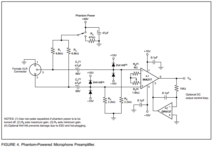
Following the signal path (As I understand it): the INA217 is an instrumentation amp, so an input transformer is not a must for a good result. Then phantom power is injected, but blocked from touching the IC input by those 2 caps in series with the signal, then some diodes for overcharge protection, the IC itself doing the work, and then an unbalanced output.

My questions:
[list type=decimal]
[*]The phantom power has a cap and a resistor besides the switch, going to ground. What is their function? Filtering? In the "off" position why does the connection goes to ground instead of nothing?
[*]The protection diodes, why they go to +15 and -15 instead ground?
[*]I don't quite get the role of R4 and R5, or the 0.1 uF caps going to ground from the power rails
[/list]

And the final one here because it's longer: I don't really get how the DC servo/offset loop works, why is there a 1M resistor, then the parallel cap and the op amp (I've just a little grasp of what a DC offset is, so maybe this doubt is just natural). I've seen some recomendations of just shunting the ref pin to ground and using a good quality output cap; that should work for me, but I still want to know how the servo works.

That's it, sorry for the numerous questions, but I'm just returning to this (I made a some DIY a few years ago), with lots of forgotten stuff and much more that I just never knew. Thanks for your answers!
 
We just went over that yesterday, see:
http://groupdiy.com/index.php?topic=56642.msg722991#msg722991

Note that there are two different ground symbols - the XLR pin1 to chassis & 48V common, the other to the audio circuit common.
 
Thanks! That design note looks like a good lecture. Also I totally forgot about the reactive properties of capacitors and how they can be used to block DC or bypass AC, so that's some questions answered for me. I'll be back after reading the design note, thank you!
 
Hi again! The design note gave me good insight about the implementation of a phantom power switch and its interaction with attenuators, and how everything is part of the load "presented" to the microphone. Another question: What would be the difference using non-polarized v/s polarized caps? For example, in the TI reference they use a P-cap going to ground (Phantom Power, I assume that's for bypassing AC noise); is this mandatory, or is just because P-caps are cheaper and using a NP-cap is not necesary there? Also, the (1) note regarding the use of NP-caps if the phantom is to be turned off intrigues me, and why NP-caps are used in the +15/-15 rails, while their use seems to be the same as in the +48 phantom power.
 
I think R4/R5 and C2/C1 form a high pass filter that allows it to pass at about 1.5hz frequencies, right?
 
Polarized caps tend to be smaller at a given voltage/capacitance value, and lower volume overall. You could substitute NP caps, but you would likely need a lot more caps to equal the same capacitance.  For instance, most polymer film caps top out at around 10uF, and are almost 1 inch long and cost about $5.  In this design, you would need 10 of them!

The design note for C1 is referring to the fact that if phantom power is off, then the input is referenced to DC ground.  If the incoming voltage swings below ground, then a polarized cap will be reverse biased.  You can find 'non-polarized' / bipolar electrolytic caps for C1 and C2 if you want to run it with phantom disabled.
 
  • samurai1993 said:
    • The phantom power has a cap and a resistor besides the switch, going to ground. What is their function? Filtering?

    • Yes filtering.
      In the "off" position why does the connection goes to ground instead of nothing?
    It allows C1 and C2 to discharge after phantom power has been switched off.

    • The protection diodes, why they go to +15 and -15 instead ground?
    If they went to ground they would clip signals larger than about 0.6V peak, and would introduce distortion even before clipping.

    • I don't quite get the role of R4 and R5, or the 0.1 uF caps going to ground from the power rails
    R4/5 are reference resistors for the input pins of the chip, so it's 'knows' they are at zero voltas normally. The small caps are standard practice for ICs; local decoupling to discourage oscillation.

    why NP-caps are used in the +15/-15 rails
    You can't buy polarized 0.1uF caps, even if you wanted to.
 
> You can't buy polarized 0.1uF caps, even if you wanted to.

Mouser.com comes back with 76 matches. Example  Nichicon UVR2A0R1MDD1TA. It is 0.1uFd (100V), it has a "-" stripe down the side. Looks polar to me. 5000 in stock.

Historically we "ALWAYS" used 0.1uFd caps every few chips, to keep the rails stable out past MHz.

0.1uFd electrolytic have been around a while but had no cost advantage over ceramics, often cost a penny more, and we questioned their suitability. (Electrolytic polar becomes THE way to go above part-uFd and below radio frequency.)

Lancaster TTL CookBook says "disk" (ceramic), which were a known-thing at the time.

Lancaster CMOS book says 0.1uFd but not what type.

More recently stacked-ceramic in boxes or blobs are widely used.

Electrolytic caps of the old days *could* have high ESR and stray inductance. Tantalum was better but came and went with bell-bottom pants. Interestingly present small Al electrolytics are about as good as any of these, and would probably be fine here.
 
The protection diodes, why they go to +15 and -15 instead ground?
If they went to ground they would clip signals larger than about 0.6V peak, and would introduce distortion even before clipping.

My newbie, pay-it-forward explanation given to me by gdiy goes something like this: 
Imagine you get a spike of -20v on one of your input signal pins.  Since -20v is +5v with respect to the -15v rail, the -15v rail would act as a 'ground' and sink that extra voltage before it reaches the op-amp input.  Same goes for positive spikes and the positive rail.
You need AC swing to utilize the op amp, and the diodes allows this swing up to, but not exceeding +/- 15v.

Edit:
but I still want to know how the servo works.
https://groupdiy.com/index.php?topic=46805.0
 
PRR said:
Example  Nichicon UVR2A0R1MDD1TA. It is 0.1uFd (100V), it has a "-" stripe down the side. Looks polar to me. 5000 in stock.
0.1uFd electrolytic have been around a while
Woah I stand corrected... who on earth is using such devices, I wonder??
 
re: "The protection diodes, why they go to +15 and -15 instead ground?"

If they went to 0V then your signal swing would be clipped to approx +/- 0.7 Volt ( a diode drop).
You don't want that unless you want a fuzzbox.
( It is appropriate for some non-audio high gain applications where you know the signal should be small).

Diodes to Ground there would need to be "back to back" Zener diodes.
If you're concerned with possible Phantom Power fault conditions then read this AES Paper from THAT (I think it's al;so mentioned in the design note from the other thread).
http://www.thatcorp.com/datashts/AES7909_48V_Phantom_Menace_Returns.pdf
 
>>> You can't buy polarized 0.1uF caps, even if you wanted to.
>> 0.1uFd electrolytic have been around a while
> who on earth is using such devices, I wonder??


I dunno. But I just came across, not 0.1, but the next best (least?) thing, a 0.25uFd in 1964. In Australia. (Scan is poor so I superimposed a blow-up.)
 

Attachments

  • 0.25uF-1964.gif
    0.25uF-1964.gif
    49.5 KB · Views: 18
Back
Top