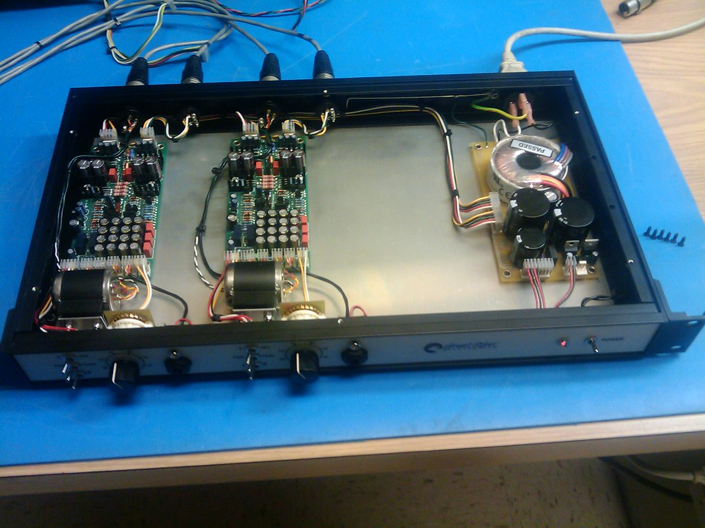
Great River MP-2 , info, schematics & discussions

GroupDIY Audio Forum

Help Support GroupDIY Audio Forum:

This site may earn a commission from merchant affiliate links, including eBay, Amazon, and others.
Double / triple check the input xfmr wiring , there is no switch
for impedance , just wire them 1:5
the ground is only for shielding , you can try to break
the ground to the input xfmr  , the xfmr unbalences on the
board

Are the relays in the correct way ?
 
Just wondering what sort of power transformer would be adequate. i have a 20-0-20 15VA - would this be OK? Or if someone could provide info on the range that would be OK that would be great.
Cheers - I'm looking forward to this!
 
from the  first post in this thread:
okgb said:
power xfmr requirements = An off the shelf 30va 22 + 22 transformer will power this up fine
you don't need to build the supply in the schematic , although it is nice with o/l l.e.d. drivers

Good supply design with comparitors for overload [ they work nice ]
though they are they only part that is surface mount size [ on psu pcb ]
Simple " raw dc " psu design cam be used  with 22-0-22 30va psu Xfmr

 
i would think you could get away with the voltage but the VA looks low
and why not get all the headroom you can make the most of the circuit
 
Well it looks like it is my turn for the redundant questions forced on by limited understanding.
I am just about done with this little beasty. Before I blow anything up I would appreciate some clairity.

A. Am I correct that J8 (power) is wired as follows?:
1-Led Driver  It looks like I have pin 1 & 5 mixed up.
2-Neg 30v
3-  0v
4-Pos 30v
5-48v
I have it this way with no smoke. No heat either, and the Led Driver is not in place as I am using a JLM power station and transformer for now.

Next up is regarding setting R48:
With a 2k pot in place, the power is turned on and I measure "dc offset" at pins 3 & 4 on audio output to the tune of less than .5mV on my meter.
B1. Do I need to have anything selected such as gain in order for this to work?
B2. Or signal coming in?

C. In regards to grounding to the PC boards. Am I understanding correctly that a wire from the ground buss wire (also attached to pin 1 at XLR) is to be run to pin 1 at the output of the pc board?

D1. Finally (Oh is it ever the last one...) when using a transformer and wanting to parallel to a 1/4" output as an option, how are things wired to remain in polarity?
D2. Pin 4 to tip and 3 to shield? or opposite?

Thanks for your time in advance.
JP
 
Thanks for that - I can't find a 22-0-22 transformer here, but I can get a 20V 30VA so that should suffice.
Is it OK to use BC547 or BC549 as substitutes for the BC107 - different package but still OK?
Also is R47 20R or 10R as they are different on BOM and schematic? 1W Carbon film OK for this one?
Thanks again
Cheers
 
as i had the same question with the trannys you can use a 22-24v power transformer.
this one on digikey "Product Number": TE62075

One man here did the power supply with a JLM Powerstation where you can adjust the
power to get the needed votages but you can build it with a few elkos yourself...

With the 10 1w  i have the same problem. im unsure cause there was no resistor in the mp2 kit to fit this last hole.
the bom says 10 and on all pictures i can see that they used 20 like the other ones... but i had no 20 in the kit too.
so i must buy it. i will take 20 cause all pics i saw used it instead of 10... dont know why but cant be wrong doing the same :)

hope i could help

aaron
 
Thanks Ptown but i had just 5 in my kit and need 6. So i´m gonna buy this one to get it done. Can you tell me what kind of resistor it is that i can order it? All the other rest is complete and done.. thanks.
Thank you. Aaron
 
You mean i can let it stay blank?
grmp2.jpg
 
If you look at the schematic, you'll see that you don't need it. The output connector has 4 pins instead of three, just ignore the one that the 10R should be connected to.
 
So I managed to blow up Q13 on one of my channels. I was set to measure offset with a 5k pot in R48, pin 4 to ground, 1&2 to my meter at the output. No OP transformer in circuit, no signal, just turned on. As soon as I gave it power "snap" and half the transistor blows off. Cool, but I don't want to do it again. So what the heck caused that? Power is right, (I am using a JLM) and I can find no shorts on the board, I've been careful about component placement...
I figured I'd drop the ground on output pin 4 and try again on my other board. This time no explosions, but I am getting an OL on the meter. I am feeling no "heat" on any components as some have described. Am I doing this procedure right?
So before I blow anything else up I am off to buy some more transistors and hoping someone can guide me better than I am doing myself.
And answer at least one of my own questions from my former post, I noted that I had pin 1 and 5 mixed up on the power input.
As always thanks.
JP

 
finally got my boards all put together.  I fired it up with the 2k pots in place of R46, everything seemed fine, checked and double checked the power wiring before i turned it on.  I haven't hooked up the XLR in, or the output transformer and i was doing the calculate R46 and checking the DC offset at the output (with nothing hooked up)  my only question is, with the trimpots in place, i was measuring about -3mv DC at the output on both channels before i adjusted any trimpots, is this normal?  before i put the trimpots in i measured them at about 2.4K for one and 2.6K for the other.  Just wanted to make sure i didn't do something wrong.

rock on and thanks for this wonderful project
 
Back
Top