


Rockitdog
Active member
Hi everyone. I'm wondering if anyone can help me?
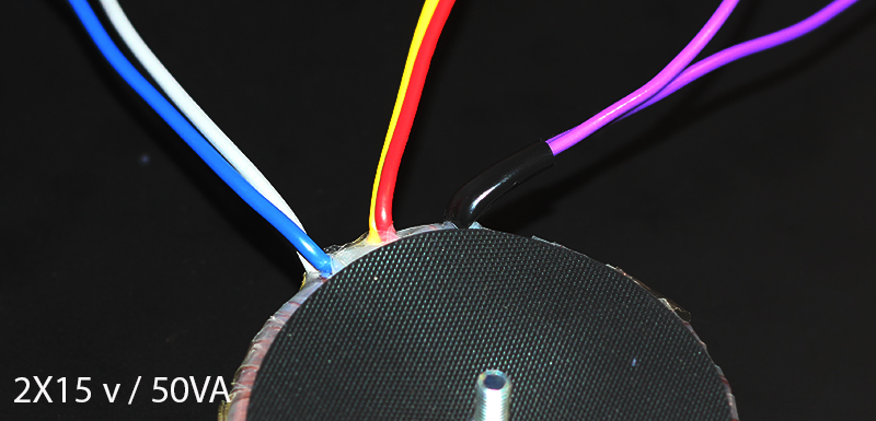
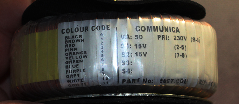
I'm fitting the power transformer for my gssl and I'm a little confused as to the correct configuration. Looking at the guide on the side off the transformer, it does look very obvious. According to the key on the secondary I join the red and yellow wires (2-5) for the one 15v rail. And join the Blue and the grey together (7-9) for the second 15v rail? Right?
My question is, what about the 0v "center tap"?
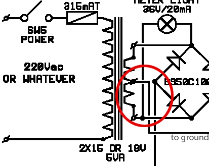
The schematic also shows the center 0v rail going to ground. And every image I have looked at shows the center rail coming directly from the transformer. I cant find wiring configuration diagrams anywhere for this transformer. Do i need to configure it differently to get the 0v rail? But what color's do i join together to get 15 - 0 - 15??
(I know this is kinda obvious, just wanted to be super clear so its easier to help me)
Can i simply run a ground wire from the center of the power pads on the pcb straight to the chassis ground?
Or do I need to buy a different transformer?
The answer is probably quite logical, I'm just nervous working with transformers (100% sure before flicking any switches). This is only the second one I am fitting and the first had a very clear wiring diagram on the side. I've also been wading through this thread for weeks and haven't come across anything specific enough to help me.
Please, if anyone can put me out of my misery it would be greatly appreciated.
Thanks in advance
I'm fitting the power transformer for my gssl and I'm a little confused as to the correct configuration. Looking at the guide on the side off the transformer, it does look very obvious. According to the key on the secondary I join the red and yellow wires (2-5) for the one 15v rail. And join the Blue and the grey together (7-9) for the second 15v rail? Right?
My question is, what about the 0v "center tap"?
The schematic also shows the center 0v rail going to ground. And every image I have looked at shows the center rail coming directly from the transformer. I cant find wiring configuration diagrams anywhere for this transformer. Do i need to configure it differently to get the 0v rail? But what color's do i join together to get 15 - 0 - 15??
(I know this is kinda obvious, just wanted to be super clear so its easier to help me)
Can i simply run a ground wire from the center of the power pads on the pcb straight to the chassis ground?
Or do I need to buy a different transformer?
The answer is probably quite logical, I'm just nervous working with transformers (100% sure before flicking any switches). This is only the second one I am fitting and the first had a very clear wiring diagram on the side. I've also been wading through this thread for weeks and haven't come across anything specific enough to help me.
Please, if anyone can put me out of my misery it would be greatly appreciated.
Thanks in advance


![Soldering Iron Kit, 120W LED Digital Advanced Solder Iron Soldering Gun kit, 110V Welding Tools, Smart Temperature Control [356℉-932℉], Extra 5pcs Tips, Auto Sleep, Temp Calibration, Orange](https://m.media-amazon.com/images/I/51sFKu9SdeL._SL500_.jpg)


 i swapped to cables on the 10 pin connector to the frontcontrols