GSSL HELP THREAD!!!

GroupDIY Audio Forum

Help Support GroupDIY Audio Forum:

This site may earn a commission from merchant affiliate links, including eBay, Amazon, and others.
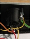
Make your safety ground connection to the case a solid connection, capable of standing fault currents flowing if anything should go wrong. From your pic your XLR-pin1 connections actually don't connect to your case as well.
Twist each pair of audio input wires connecting to XLR-pins2/3, so the balanced line receivers have a better chance to cancel out induced garbage from FI a radiating mains transformer or whatever radiating nearby source with your case open.
What was the source of your 12V? feed that blew up the 7915. If it was taken from this GSSL build, chances are one diode inside the small bridge rectifier might be blown from the overcurrent that killed your wrong connected 7915, now causing your noise/hum/hiss.
You already double checked all 5 supply rails for correct DC voltages?
 
I've doubled checked the grounding and it's fine. I get good continuity between pin 1 on every XLR connector and the case. Also the earth pin on the IEC socket is connected to the case and measures good continuity.

The 12v source i used when playing around with my old regulators came from my converted ATX powersupply which i use as a benchtop power supply. I did not use 12v from the board.

I have measured every pin on every IC socket and this is what i found: If I don't specify + or - voltages then assume it is positive. If i don't mention a specific pin then assume it measured at 0.00v

TL074 Quod op-amp:
Pin 1: 2.4v
Pin 2: 2.6v
Pin 3 0v
Pin 4: 12.34v
Pin 5: 0v
Pin 6 started at 1.55v but descended whilst measuring (capacitor discharge?)
Pin 7 started at 1.40v but descended whilst measuring (capacitor discharge?)
Pin 8: -0.29v
Pin 9: -0.20v
Pin 10: 0v
Pin 11: -12v
Pin 12: 0v
Pin 13: 2.64v
Pin 14: 2.87v

TL071
pin4 -12v
pin8 +12v

Alone THAT 2180B (in between TL074 and TL071)
pin1 1.35v but descending slowly with meter connected (capacitor discharge?)
pin2 12.33v
pin3 0v
pin4 -7.93v

LEFT VCA
5534:
pin4 -15v
pin7 +15v

LEFT VCA
THAT 2180B
pin5 -14.90v
pin7 15v
pin8 0.84v

RIGHT VCA
5534:
pin4 -14.98v
pin7 15v

Right VCA
THAT 2180B:
pin5 -14.90v
pin7 +15v
pin8 -0.07v

NEAR balanced output:
5532 (nearest edge of PCB)
pin1 -0.84v
pin2 +0.84v
pin4 -14.98v
pin6 0.80v
pin7 0.77v
pin8 +15v

5532 (directly bellow balanced output molex connector)
pin 4 -14.98v
pin8 +15v


NEAR balanced input:
5534 (near edge of PCB)
pin4 -14.98v
pin7 +15v

5534 (in the middle)
pin4 -14.98v
pin7 +15v

I hope I have displayed the location of each chip properly. Any questions about any of the measuring points please ask. Any anything that looks unusual please let me know! Thanks you for all your help so far!
 
jameslangtry said:
I've doubled checked the grounding and it's fine. I get good continuity between pin 1 on every XLR connector and the case. Also the earth pin on the IEC socket is connected to the case and measures good continuity.
Maybe. Your latest pic shows a lottery/unsafe fixing.
jameslangtry.jpg


I have measured every pin on every IC socket and this is what i found: If I don't specify + or - voltages then assume it is positive. If i don't mention a specific pin then assume it measured at 0.00v
...probably with ICs fitted and without audio/testtone signal (at whatever level and frequency) connected to the input.

TL071
pin4 -12v
pin8 +12v

Alone THAT 2180B (in between TL074 and TL071)
pin1 1.35v but descending slowly with meter connected (capacitor discharge?)
pin2 12.33v
pin3 0v
pin4 -7.93v
There is no TL071 (single opamp) in this build. TL072 (dual opamp needed). Probably only typo.
Voltages/pin numbers look mixed up and this type of VCAs are current, not voltage operating devices, IE current in/current out.
 
There is no TL071 (single opamp) in this build. TL072 (dual opamp needed). Probably only typo.
Voltages/pin numbers look mixed up and this type of VCAs are current, not voltage operating devices, IE current in/current out.

Not a typo. A genuine mistake! How utterly stupid of me. Considering I always double checked the component layout diagram every time I replaced ICs. Oh dear. I deserve a bullet. Put a TL072 in and now everything I fine. The horrid noise is gone and everything is working as it should (i think).

Tomorrow morning I will run some test signals through and check that the unit is actually compressing.

Once again, thanks for all your help Harpo. Couldn't have sorted this without you!
 
Hi. I have one question for GSS power supply. Why do I need in the PSU resistors 10R between  filter capacitors  and 22R output and input 7815 78L12?. Thank you for the help.
 
Hello,

I build GSSL on new board from Gustav. And is't work ok. I have a strange noise something like oscilation what ever. I have all power rail with a good voltage and I have double checked  for shorts everything looks ok. When I get out That's and connect 1 - 8, disconnect controls  it sill sounding bad.
This is drums recorded by my gssl You can hear it.

https://www.dropbox.com/s/khrl4r2073lw2wm/ssl%20error.mp3

Please tell me where I should start checking for mistakes.

thanks for help !!!!
Artur
 
Artur, check your connections to GSSL and from GSSL to the next piece of gear. Might be related to balanced/unbalanced connections and probably noone can hear an open or shorting solder connection. IE XLR-in-pin3 connects to ?, XLR-out-pin3 connects to ? ...
 
I have my ssl outside the case because im waiting for delivery. Connections seems to be right. I use it with rme fireface 800 and there all ins and outs are balanced. The noise is going heaver when i use thres. pod lower noise is quieter higher thres. more that noise.... I found that I have wrong resistor 1K neer VCA. I have 1,02K instead 1K... Maybe this ??? Now I damage one that and on one channel I have only a feedback... :(
 
Hi,
This might be an interesting question/error.

I've built the GSSL, with super-sidechain. Voltages are good. No latching rails. But no audio. Silence on both channels!

So I traced the signal and its there and ok on both channels all the way up to the VCAs pin 1 Input. So, it gets to the 27k resistor just before VCA ok, and then after the resistor its dead.

So i check if its getting grounded for some reason. Here's the thing, it is, but only when compressor is On with power in the rails. If the compressor is powered off, there is no continuity to ground on pin1 of VCA. I'm using 2180B. So this seems to be related to some type of active component? IC? Relay?

Any ideas?

Thanks!
 
dalmaproductions said:
. So, it gets to the 27k resistor just before VCA ok, and then after the resistor its dead.

The that chips have current in / outputs. Have a look in the datasheet.
It is normal to measure no voltage after both summing resistors when the chip is in place.
 
No signal after the VCA, at pin 8, or NE5532 pin 7  ???

Could an invalid Control signal from the sidechain cause the VCA's to behave like this? Any other ideas?
 
Hi Guys.
I had some problems with my voltages on my GSSL. I had change the 7815 and 7812, and the voltages seems to be ok.
I test the GSSL, and... no compression. Only the makeup is working.
Any idea to fix that problem ?
Thanx.
Tom
 
@dalmaproductions: After the opamp that does the conversion from current to voltage again.
The VCA is a current in / current out device (lookup THAT218x datasheet for confirmation).
The 27K resistor does the voltage to current conversion in front of the VCA. For 0V differential between the VCAs Ec+ and Ec- ports this is the VCA bypass condition, IE current in=current out. When you imagine a 1V signal in front, the 27K resistor converts to 1V/27K=0.037mA current into VCAs pin1. From current in=current out, VCAs pin8 will pass this 0.037mA and because the VCA itself is inverting, change sign of this current number. This connects to the opamps inverting input, a virtual ground node. The opamp tries its best to hold both input terminals at same potential and as the non-inverting input is hard tied to 0V and current doesn't flow into the opamp, this current has to go to somewhere, done by the opamps 15K feedback resistor. The opamp has to raise its output voltage (pin7 of the NE5532) by 15K*0.000037A=0.5556V, so both currents (-0.037mA+0.037mA) cancel out at its inverting input.
(I am sure, a native speaker can explain this a lot better)
 
Thanks Harpo! That gave me some ideas.

I just realized i'm not getting silence at output, I'm gettin around -65dB

I am getting 440mV at the Ec- pin 3 of the 2180. So this looks a bit off. According to the datasheet, this would give something like -70dB. So I removed the TL072 to try and get Ec+=Ec- and therefore have no Control Voltage from sidechain. This gave me full signal at the output of the compressor!

So I'm guessing the problem is my sidechain.
 
Artur,

Mount in metal box before trying to judge noise.

Then sift through this thread to find similar problems - and their solutions.

This thread is an archive of possible problems and solutions - NOT a help chat.

Jakob E.
 
I'm waiting for a case. Next week I will be have and I put board inside and I will check again it. Thanks for reply.

Artur
 
Back
Top