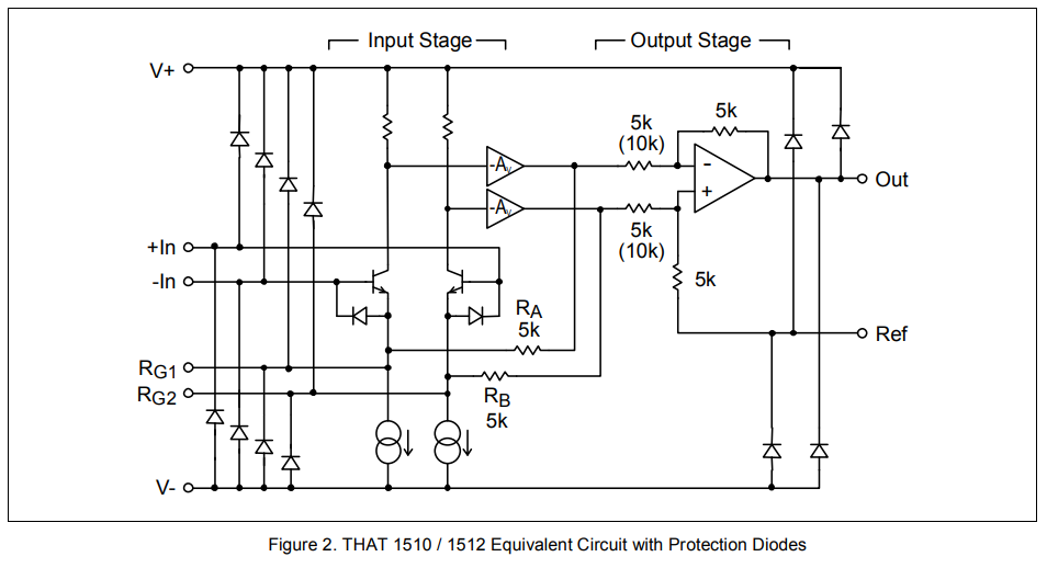
no.... the gain pot is capacitor coupled so the DC gain of that first stage is modest. The input devices are biased up at v/2 (6V?). The op amp inputs at v/4, but output is likely v/2.squarewave said:Really? But a mismatch is going to cause an offset error that could limit headroom pretty significantly no?
Another thing I just noticed about this circuit is the 7812 regulator after a diode is going to require more like 15DC supply and not 12V.
Looking at this closer I am inclined to abandon it for a better topology.
The input devices are running open loop so will distort pretty easily.
A single 12v rail will not deliver much headroom (but that is relative), so usable as long a gain is kept modest..
Better designs extend negative feedback to around the input transistors so they are effectively operating constant current and deliver much lower distortion. To do this requires at least two op amps (one for each input transistor). The second opamp could be repurposed to deliver this but it would involve a major cut and point to point kluge.
I wouldn't invest too much time, effort, or money into trying to improve this design. It's one saving grace may be it's relatively high distortion that some may consider euphonic (I don't).
JR
PS: My apologies to any who think my tone is "harsh" just calling it like I see it, after decades of designing mic preamps. 8)