How many T4's does one person need?

GroupDIY Audio Forum

Help Support GroupDIY Audio Forum:

This site may earn a commission from merchant affiliate links, including eBay, Amazon, and others.

SSLtech

Well-known member
Joined
Jun 3, 2004
Messages
5,447
Location
Florida (Previously UK)
...I mean, -really?

01-Cluster.jpg


;D

Here's the scoop.

As part of working on a project, I'm having to measure and analyse the performance of the T4 modules.

In order to do this more thoroughly, I have to trace the curves from as wide an array of T4 modules as I can possibly get my hands on.

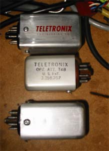
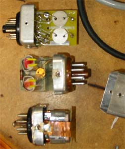
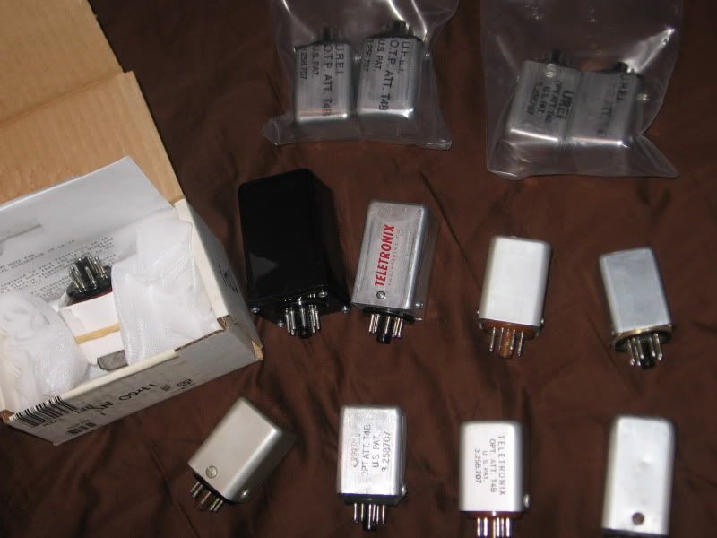
In the above picture, there's a nice array, including:

* Teletronics reissue T4 (tall can)
* Original Teletronix T4-A (tall can, with THREE photocells; 100kΩ R25)
* Original Teletronix T4-B (SHORT can, with THREE photocells; 100kΩ R25)
* Chris Jenrick T4-CJ, with two photo-cells; 25kΩ R25)
* NOS UREI T4-B
* Experimental T4 (Vactrols... R25 to be determined)
* Teletronics reissue T4 (short can)
* a selection of T4's from the JBL-Urei time period.

Also, currently plugged into the back of my LA-2a's, I have a couple of other T4's, which I'll also be measuring, comparing and evaluating.
I know that Joeelectro and a few other people have made some investigative progress with T4's in the past, but I'm really trying to make as comprehensive a study as is possible about the characteristics of T4 modules; the aging of the internal components -both the EL panel and the photocells- and any difference between photocell brands, with careful specific regard to release time and aging spread. Some are unused, others are well-used. I'm hoping to try and also see if there are any characteristics which may be age-specific irrespective of use, or 'load-specific, irrespective of age'.


now... if you want to REALLY see a lot of T4-B's... take a peep at this:

T4bs-1.jpg


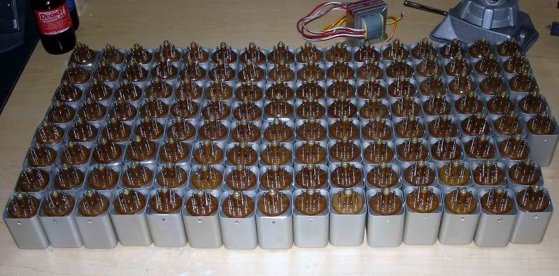
Don't get too excited though. -I DON'T OWN THESE.

These were the Bloo-T4 cases which were used years ago when Steve was selling the Bloo LA-2a kits. -All long gone now.


Keith
 
Good project, please keep us informed of any important findings if possible.  Are you purposefully leaving the Drip work out of the pic?
 
Well, the Drip ones are not significantly different to my mind, since they use the same EL panel/NSL opto combination as the Chris Jenrick version, but with one significant difference...

Chris Jenrick tested, hand-selected and matched all of his optos.

Gregory (drip) has posted that UA don't select/match their optos, but that's actually untrue, and so I conclude that his optos are just randomly supplied NSL's.

The selection procedure is particularly vital when comparing aged components, since if a difference is measured between the two optos, you cannot ascribe it to aging if you don't know for sure that the two were measured and declared to be the same at some point in the past.

Particularly significant will be measuremenets of the different type of opto-resistors. Here's a couple of  shots from the Uaudio webzine:

t4cans.jpg
 
t4sinside.jpg


In the second "nude" pic, you can clearly see the different cells used between the T4 reissue (top) the T4B (middle) and the early T4a (bottom).

I have more than one example of each of these, so should be able to come up with SOME kind of indication of how much consistency versus variety there may be.

I'm hoping for this to be a little more in-depth than the stuff from the UA website, although  I'm deeply indebted to Will Shanks for providing an excellent starting point, as well as some inspiration.

Keith
 
I thought Drip was doing some extensive matching research; found this thread:

http://www.groupdiy.com/index.php?topic=19701.msg230511#msg230511

His pics are gone, but I remember lots of charts and graphs.  Know one knows what he does now.  Seems I remember you also calling BS on one of his procedures too; do you recall which, since I can't?  Correct me if I'm wrong!  You've certainly seen and delved into more of these than anyone I know of. 
 
Well, perhaps he said that back in 2006, but in May 2007 (from this thread) he posted:

NOS t4bs  are  un matched and do differ in specs from t4 to t4.

this is a fact and is real.

So perhaps by then he gave up on the sheer magnitude of the difficulty, which when sorting through a batch of even only a hundred optos would be significant. _Depending on how much you charge for an hour of your time, measuring, logging and then matching even at five minutes to measure each opto would take over eight hours. Then add sorting and 'double-check' comparison once you've paired them off, and you're spending a LOT of time, doing some extremely tedious stuff.

But from that later post, I had to conclude that he was NOT bothering with the selection procedure.

Keith
 
From the horses mouth.

I've sent UREI's Electrical Test Spec and Procedure for selecting the CL1604 LDR for the T4 to the gmail account.

I hope it helps Keith.

strangeandbouncy said:
Tut Tut,
. . . . that's just plain greedy . . . .

If you look at the test spec, there's quite a variation in acceptable release times.

I think what Greg is saying is that you're not guaranteed to get any two T4's to match up exactly.

I have one of his T4's here in my LA2 build and it sounds fine.

With that said, I haven't compared it to any other T4's to know if there's a significant difference.

Mark
 
is your testing including distortion? I've noted over the years a wide variation in the distortion levels in UA's reissued T4. Including some that were so bad that they went in the bin....~ 5% THD
 
A related question,

inside the T4B box there is a 4700pF (or so) cap. I don't have a schematic at hand. What is this cap doing exactly? I found a significant difference in sound playing with different types of caps (mica's, PIO, polyprops) here...
 
It's not always present.

There's also another cap in series inside an LA-2a; a ceramic cap right next to the octal socket.

-I can't imagine the specific TYPE of cap inside the T4 makes much of a difference myself, especially when there's another ceramic cap (C11) right there in series with it...

But -as for what does it do?- The EL panel will light up with DC just as easily as AC. It can block DC while still passing AC. Other than that, and defining a LF rolloff corner (dependent on source and load impedances) a capacitor can do little in terms of effect other than be an imperfect capacitor. -If you put a cap in there with any inductance or leakage it light have an effect, but there's bugger-all else that it can do, really.

The corner frequency should be pretty much outside the band, because of the effect R37 has, which completely dwarfs any effect from the LF corner frequency in terms of being inside the audio band.

Earlier T4's even had different cell types for meter and signal paths, and there were fixed resistors in there also. These resistors provided a load after C11, and made the 6AQ5 (or 6005) work a little harder.

Keith
 
Oh, yes I already had a copy of the UA test and select/reject procedure, but thanks for the upload. It'll help everyone to see what the criteria are, I'm certain.
I've started on the list of tests. This is going to take a while.

It's also going to require swapping out several of the older EL panels and LDRs for new ones, to ascertain which component is responsible for what effect.

Keith
 
> It's not always present.

Matching?

Remember the glow-panel is a capacitor. Over most of the audio range, the driver Z is lower than panel Z. So if a panel makes 2X too much light per Volt of drive, and is say 100pFd, then adding 100pFd in series is a capacitive voltage-divider and will give the panel 0.5X the drive. Actual panel capacitances are higher, so the cap will be larger.

There's also tolerance in the LDR. If this cap is selected at assembly, it can trim the overall response.

This could be adjusted (I have not yet peeped the factory doc) by putting 110V AC wall-juice on the panel, reading the LDR with an ohm-meter. Say the reference reading is 5K-10K. If the gal sees 3K, she inserts a cap-box with several caps, twists to get in the 5K-10K zone, then plucks that value and stuffs it.

I think you have found a lifetime project.
 
I'm probably being naive here, but isn't there a possibility of creating a digital T4b. i.e. Divide down the input that usually goes to the EL panel, buffer it and send it into the A/D port on a uController chip, then use a lookup table to get the required response then out through a D/A port to drive something like a FET as a resistor to simulate the LDR.

Just a thought that keeps coming to mind whenever I read these threads on T4b's.
 
PRR said:
> It's not always present.

Matching?

Apologies, I could have been clearer; Different eras used them or didn't use them. As a very general declaration, later design versions always used them, but earlier ones didn't. The value is always constant.

I'm not certain that the EL panel is purely capacitive in terms of 'model', unless we mean a somewhat 'leaky' capacitor. I seem to recall that they will light from DC also, which would imply a less than purely capacitive behaviour.

I should really re-test this, to assure that I'm not misremembering, or talking out of my posterior...

solderspongebob said:
...isn't there a possibility of creating a digital T4b. i.e. Divide down the input that usually goes to the EL panel, buffer it and send it into the A/D port on a uController chip, then use a lookup table to get the required response then out through a D/A port to drive something like a FET as a resistor to simulate the LDR.

Just a thought that keeps coming to mind whenever I read these threads on T4b's.

Well the grand beauty of the T4B is that it's passive. You could build a digital model with an octal plug on a wire, but making it work would require another power supply, unless you can get some digital trickery to operate on +100VDC... ;)

Interesting thoughts, though

Keith
 
SSLtech said:
Well the grand beauty of the T4B is that it's passive. You could build a digital model with an octal plug on a wire, but making it work would require another power supply, unless you can get some digital trickery to operate on +100VDC... ;)

you could use the same circuitry thats used in those little USB wall wart chargers?
 
Back
Top