How to add sends to a forssell or nyd summing buss

GroupDIY Audio Forum

Help Support GroupDIY Audio Forum:

This site may earn a commission from merchant affiliate links, including eBay, Amazon, and others.

substitute

Well-known member
Joined
Jul 14, 2004
Messages
504
Location
PHILADELPHIA
http://www.forsselltech.com/media/attachments/8chsum_1.pdf
http://www.twin-x.com/groupdiy/albums/userpics/balancedmixnetwork.pdf

So the Manley 16x2 mixers are almost exactly what I'm looking for, 'cept they cost $8000 and I only need maybe 10 channels.  Either of the forssell or NYD designs seem easy and affordable to build and almost get me where I'm trying to go.  The only thing that's missing for me are sends, preferably two.  I've attached a little mock up drawing, it's a clip from the forssell schematic; in red I've added a "send pot" after the fader and before the pan pot.  Some questions...

-Is this the right track at all?
-What value should the "send pot" be
-Should it be before or after the buffer amp
-as for the buffer amp, any ol opamp?

as always, thanks
 
While mixer design is a little more complex than that, yes and no... Your circuit will buffer and pass signal, but there may be signal integrity issues. For the modest cost of adding a few resistors you can make the buffer amp differential, so the local ground at the pot where you grab the signal, is referenced forward to the ground at the output jack.

I like to joke that consoles are the most difficult simple circuits to design...  I'd add the extra resistors.

JR
 
Anything you can point me to research wise? 
Studying this...
http://en.wikipedia.org/wiki/Operational_amplifier_applications#Differential_amplifier

It's not clear to me how to start figuring those values, I figure the input impedance is 5k, and voltage would be 5v for line level, the other resistor values are a totally new thing to me.

I like to joke that consoles are the most difficult simple circuits to design

I'm getting that.  There's quite a few threads regarding summing or diy consoles and what not most of them kind of dead end.  If there was a commercial product at a price point I could afford I'd be all over it.  Adding sends doesn't seem too ambitious, but we'll see.
 
substitute said:
Anything you can point me to research wise? 
Studying this...
http://en.wikipedia.org/wiki/Operational_amplifier_applications#Differential_amplifier

It's not clear to me how to start figuring those values, I figure the input impedance is 5k, and voltage would be 5v for line level, the other resistor values are a totally new thing to me.
First thank you for searching... there is a world of information at our fingertips these days.
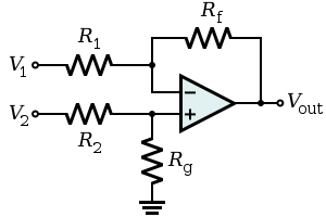
300px-Op-Amp_Differential_Amplifier.svg.png

Looking at the image I borrowed from wiki, the way to reference a signal between two grounds is to connect the source or local ground to V1 node, with the output ground that we are sending to connected to the ground symbol, "and" insure the ratio relationship that  R2/Rg = R1/Rf.  You can deliver gain in this differential stage by the ratio of Rf/R1, with equal values giving us unity gain. So for gain or loss vary both resistor pairs the same amount.

Note: these resistor strings just care about the ratios not the actual values so you can vary each string for optimal loading, or noise considerations. 

I like to joke that consoles are the most difficult simple circuits to design

I'm getting that.  There's quite a few threads regarding summing or diy consoles and what not most of them kind of dead end.  If there was a commercial product at a price point I could afford I'd be all over it.  Adding sends doesn't seem too ambitious, but we'll see.

There are modern chip sets that make nice balanced input/output circuits, often better than we could roll on our own, because they can take advantage of precision matched resistors inside the ICs.

JR
 
First thank you for searching...
It's literally the least I could do...

the way to reference a signal between two grounds is to connect the source or local ground to V1 node
I didn't understand this at first, googling "local ground" was fruitless, but "reference a signal between two grounds" brought up this...

http://www.allaboutcircuits.com/vol_3/chpt_8/2.html

The two input leads can be seen on the left-hand side of the triangular amplifier symbol, the output lead on the right-hand side, and the +V and -V power supply leads on top and bottom. As with the other example, all voltages are referenced to the circuit's ground point. Notice that one input lead is marked with a (-) and the other is marked with a (+). Because a differential amplifier amplifies the difference in voltage between the two inputs, each input influences the output voltage in opposite ways. Consider the following table of input/output voltages for a differential amplifier with a voltage gain of 4:

They have some diagrams and charts as well that illustrate the difference (is that potential?) between V1 and V2 multiplied by a constant (which is determined by the resistor ratios) and how that affect Vout. 

So that's making pretty good sense, Thanks John!

Just to make sure I'm still on the right track... I want the input impedance of the buffering amp to be high, 10k?, and I don't really need any gain from it. 

Seems, like I should get some parts and bread board it.  Would I need to bread board all 8 channels of the mixer or could I just do a few?


Opamps are so popular because you can execute simple designs from manipulating resistor values and ratios, with little deeper understanding, and this is OK when starting out.

For a little more explanation about how the differential reference works, the differential amp has + and - feedback network inputs.  The local signal connects to the local + net input. The local signal ground or 0V reference connects to the - net input. For equal value resistors the gain of signals for both inputs is unity (+1 and -1 respectively for + and - net inputs). 

But a little closer look at how that unity gain comes about is useful. Opamps with negative feedback (feedback resistor networks like Rf) connected between opamp output and opamp - input terminal, convert the huge open loop gain of the raw opamp, (often >100k to 1) into making the - input follow very closely any change in the + input.  So if we visualize a 1V signal coming into the + net input with both grounds at the same 0V, we get 1/2V at the + input due to the simple resistor divider formed by two equal value resistors. Since NF makes the opamp - input follow, it too will be 1/2V. SInce the - input of the opamp doesn't sink or source significant current from inside the opamp, the current flowing from that opamp - input voltage to ground, must be coming from  the feedback resistor resulting in 1V at the output.

Now the interesting part, and how the circuit references the two grounds to each other, imagine that there is voltage difference between the output ground and the local or input ground. The resistor between the opamp + and the output ground, looks like another + net input to the unity gain differential amp. So that voltage difference gets first divided by two and presented to the opamp + input, then gets doubled in the opamp output by the NF network, so in effect, any voltage difference between the two grounds, gets added 1:1 into the final output voltage, so the signal at the output relative to the output ground is exactly the same as the input signal relative to the input ground.

I hope this makes sense.

JR
 
Back
Top