Hi! today i finished a pair of pres which i started 3 years ago, but for many reasons i couldnt finish before
My 2 channels are working, no noise, incredible amount of gain(which i think it is a bit extreme)
Here is the link from the project
http://www.schwenkleraudio.com/hybrid312/
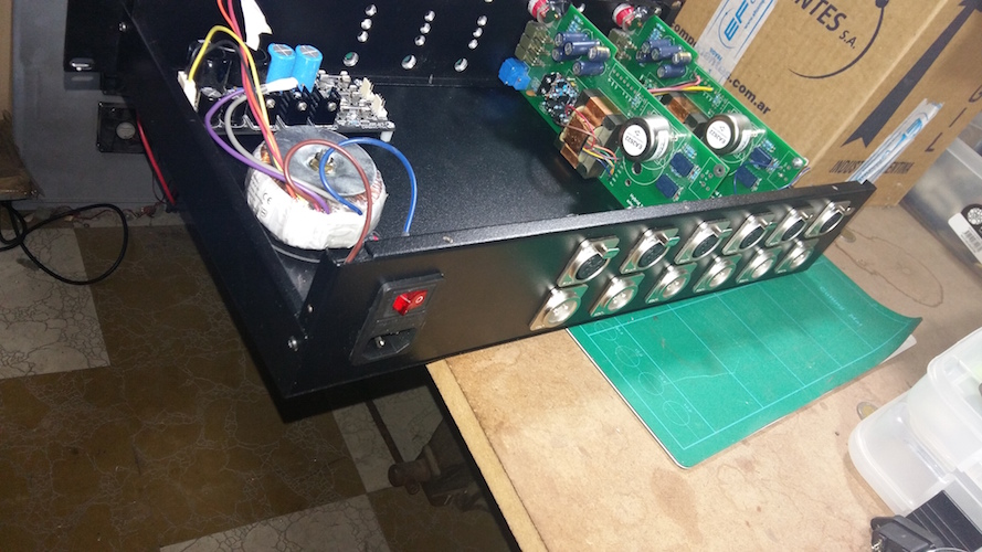
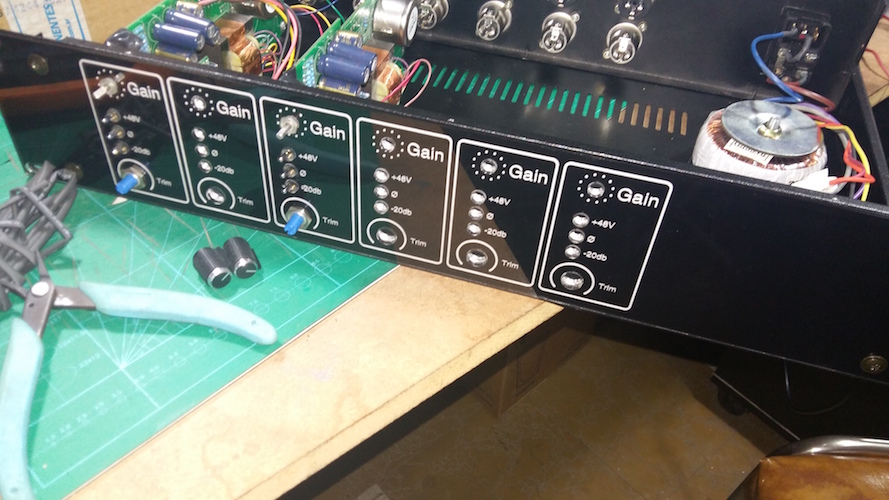
Some photos of 2 days ago
I wanted to ask a few questions anyway,
1: Relays Bob used on the BOM which are the one i bought
Panasonic TQ2-12V and in the PCB is marked as 15v supply, i am using a 16v supply actually(five fish audio 2448 set to 16v)
Isnt using 15v on a 12v relay a little dangerous for it? if it is accepted, would the 16v positive work too?(i will have to make a 6 voltages power supply later anyway)
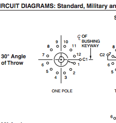
2: Grayhill Switches:
I am using them, but... i cant find anywhere the pin to make the rotary stop, but i dont know and i cant find information about this. can i use a resistor leg and cut it? and, i should place it on position 12 ?
3. I am making more these months since i really like them and want to try making one with 990s and other one with some older 2520 or melchor DOA and some different transformer(to get another type of sound), for 990, i wanted to know which output transformer i could use which would fit in a 2503 place? i was thinking in some jensen, but dimensions arent right, they are a little too big for this PCB. For input i will use some CMMI2c from cinemag, or Jensen JT 16 B i guess it was the model(have to check it out before buying anything).
4. I am getting quite an extreme Gain, i already get a good lvl for microphones with minimum set of gain from grayhills, maybe i have to trim the trimpots a little(havent dont that yet), converters used are SSL Alpha Link MX, set ut 16dbu. I hope i didnt confuse in any resistor on the chain, will have to check it later.
Thank you and i really like these pres on the little things i could try, some vocals of mine and with a guitar and DI box, which i am no guitarist. I got them working just 4 hours ago") so i am all fired up.
so i am all fired up.
My 2 channels are working, no noise, incredible amount of gain(which i think it is a bit extreme)
Here is the link from the project
http://www.schwenkleraudio.com/hybrid312/
Some photos of 2 days ago
I wanted to ask a few questions anyway,
1: Relays Bob used on the BOM which are the one i bought
Panasonic TQ2-12V and in the PCB is marked as 15v supply, i am using a 16v supply actually(five fish audio 2448 set to 16v)
Isnt using 15v on a 12v relay a little dangerous for it? if it is accepted, would the 16v positive work too?(i will have to make a 6 voltages power supply later anyway)
2: Grayhill Switches:
I am using them, but... i cant find anywhere the pin to make the rotary stop, but i dont know and i cant find information about this. can i use a resistor leg and cut it? and, i should place it on position 12 ?
3. I am making more these months since i really like them and want to try making one with 990s and other one with some older 2520 or melchor DOA and some different transformer(to get another type of sound), for 990, i wanted to know which output transformer i could use which would fit in a 2503 place? i was thinking in some jensen, but dimensions arent right, they are a little too big for this PCB. For input i will use some CMMI2c from cinemag, or Jensen JT 16 B i guess it was the model(have to check it out before buying anything).
4. I am getting quite an extreme Gain, i already get a good lvl for microphones with minimum set of gain from grayhills, maybe i have to trim the trimpots a little(havent dont that yet), converters used are SSL Alpha Link MX, set ut 16dbu. I hope i didnt confuse in any resistor on the chain, will have to check it later.
Thank you and i really like these pres on the little things i could try, some vocals of mine and with a guitar and DI box, which i am no guitarist. I got them working just 4 hours ago
so i am all fired up.