[quote author="JohnRoberts"]
HUH?
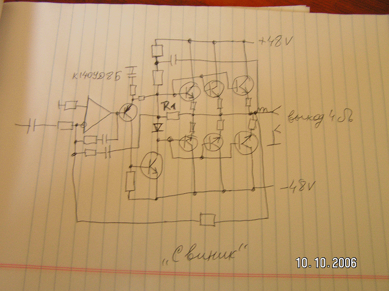
The schematic you posted looks like it might be a crude quasi-complimentary output stage if you make the three lower power device into PNPs. However still not remotely like the Cordell MOSFET output stage's error correction/linearization topology (which was also class AB IIRC).
[/quote]
1. Bob Cordell's design has nothing to do with A+D approach described in the patent.
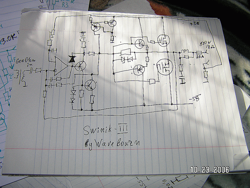
2. What I've posted, is the similar approach, but instead of supplying floating power for class A, class C works on the load directly (class A works on the load through R1). It is simplier, but sounds better.
And indeed, bottom transistors are PNP. It is class C complementary voltage follower. I have to stress that it has to work in class C, not in class B! It sounds better when a diode between bases is removed, but consumes more power. The idea is, crossover points must be on higher possible output power.
No crossover point close to zero power must be allowed for the audio amplifier!!!
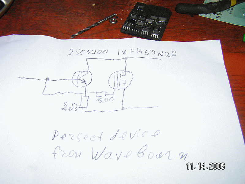
Here is my "Tango" pair I used for a later 3-step approximation:
Walker used similar approach in his "Current Dumping Audio Amplifier". It used 2-step approximation, like my first Swinik.
And in conclusion, all this means dances around old good class A amp trying to breed it with something else in order to save some electricity and to patent everything that is not covered yet by asphalt...


