I'm losing my mind trouble shooting Hamptone JFET

GroupDIY Audio Forum

Help Support GroupDIY Audio Forum:

This site may earn a commission from merchant affiliate links, including eBay, Amazon, and others.

substitute

Well-known member
Joined
Jul 14, 2004
Messages
505
Location
PHILADELPHIA
Hey friends,
I bread boarded the tapeop hamptone jfet circuit a while back. I had it configured as two of the amp stages cascaded,  everything worked great. I liked it so much I built the summing amp circuit in the article on strip board and transferred my breadboarded circuit to strip board as well. Now they're not working and all four instances of the basic amp are failing in the same way. The ZTX653 is rapidly overheating. Every fibre of my being says this has to be a layout issue, some mistake I made in transferring the schematic to strip board, but I can not find it to save my life and it's not like this is a complicated circuit.

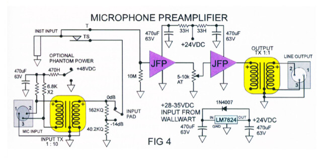
Here's the original article...
https://tapeop.com/interviews/37/diy-jfet-mic-pre/

And here's a drawing of my layout. This is copied from the strip boards themselves after I started trouble shooting.
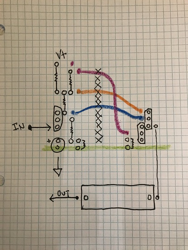
50037718698_366e71f622_c.jpg


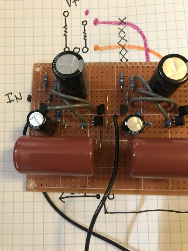
Here's a pic fwiw
50038263946_958c3f7235_c.jpg


So, maybe another set of eyes will catch what's right in front of me. Also, any general ideas as to what would cause that transistor to overheat.

Many thanks-
 
ruffrecords said:
Not really my field but don't you need a resistor from the input FET to 0V  ? else it is floating in the wind.

Cheers

Ian

Good observation, on the breadboarded version I had a 10M resistor wired up on a 1/4 jack I was using for the input. I don't have that setup yet on the stripboards, I was just alligator clipping from my function generator to the input and attempting to scope the output when all went haywire.
 
substitute said:
Good observation, on the breadboarded version I had a 10M resistor wired up on a 1/4 jack I was using for the input. I don't have that setup yet on the stripboards, I was just alligator clipping from my function generator to the input and attempting to scope the output when all went haywire.

Without it the bias will be shot to pieces and not surprisingly some transistors could get hot.

Cheers

Ian
 
47k from +24 to base of the CCS (constant current source) results in 500uA in the base and probably the CCS trying to sink about 100mA from the upper transistor, no wonder they are getting hot. This resistor should be at least 10 times higher.
 
Hard to tell what's going on in your layout. What's the value of the resistor going from V+ to the circuit? I'm assuming you're using that for power isolation? I'm also assuming the large electrolytics not on your layout  go from there to ground? What voltage do you have before and after your isolation resistor? These sections should only draw around 40mA each.

And yes, you need some kind of input termination (1M-4M7 works fine).
 
If it helps, there are some small changes you can make to the output section of the Hamptone to adjust the current to not murder your transistors all the time. It's the LED and diode (D2 an D3) in the schematic a few pages down here: https://docs.google.com/document/d/16242mJW2ZmwldvevZ6Yy1l5WBadvsuWd13oR7KGU258/edit


EDIT: Also I was advised to use physically large transistors and even something with a heat sink. Have you checked the data sheet for the package you're using to see if they can handle the kind of current you're running through them?
 
abbey road d enfer said:
47k from +24 to base of the CCS (constant current source) results in 500uA in the base and probably the CCS trying to sink about 100mA from the upper transistor, no wonder they are getting hot. This resistor should be at least 10 times higher.


I can confirm that 47K works just fine in this circuit (I've built many variations of it). If you were to increase it to 10 times higher, you'd increase the output impedance, lose drive capability, and almost certainly clip the signal.
 
I put the 10m bias resistors in place but I believe I fried the jfet (and possibly the output transistors) not having them in place. On the Jfet I've got 0.5v on the drain, 0.5 on the gate, and 27v on the source.  I seem to have let the smoke out.
 
OneRoomStudios said:
I can confirm that 47K works just fine in this circuit (I've built many variations of it). If you were to increase it to 10 times higher, you'd increase the output impedance, lose drive capability, and almost certainly clip the signal.
With 47k, the output stage could probably drive a 10 ohms load; is it really what you need? I say could, because the 1st stage would give up before.
Do the others work cool in the same conditions? Same 24V supply?
 
substitute said:
I put the 10m bias resistors in place but I believe I fried the jfet (and possibly the output transistors) not having them in place. On the Jfet I've got 0.5v on the drain, 0.5 on the gate, and 27v on the source. 
  Really? Are you sure you haven't got your FET pins mixed up? The highest voltage should be on the drain. And it should be about half the supply voltage.
So, the voltage rail is not 24V, is it?

 
I seem to have let the smoke out. 
  But does it work? I don't think it does really well.
 
..please note that the market is currently flooded with fake jfet transistors - I've even had a batch from a reputable vendor earlier this year. It's usual to get some generic npn bipolar, falsely laser marked not screen printed.

Related thread: https://groupdiy.com/index.php?topic=75429

You may want to check.

/Jakob E.
 
  Really? Are you sure you haven't got your FET pins mixed up? The highest voltage should be on the drain. And it should be about half the supply voltage.
So, the voltage rail is not 24V, is it?

The supply is 24v. I have no explanation for the 27v measurement. As far as the pins, it never hurts to check again, but I'm pretty confident that's correct. As far as the fake jfets, size of the output transistors and general queries about the circuit itself. It worked great breadboarded with the parts I have. I didn't notice the output transistors getting hot or anything like that. I'm using this as a kind of line level driver for adding some dirt and beef to synths, which it did swimmingly.  And as far as the load to be driven, most likely the line inputs of my interface which are high z, maybe I'd run it into a pultec or la2a though, but that's still a lot higher that 10 ohms.

I forgot that you can't see the entire article without paying. For clarification here's the configuration I breadboarded minus the transformers. This schematic also shows the resistor and cap that was asked about.

50040526662_133dfafa8f_z.jpg


I think I should probably breadboard this again, tryout some of the tweaks suggested. Thank you for the help, and all the advice about output current etc


substitute said:
The supply is 24v. I have no explanation for the 27v measurement.
Tell-tale sign that something's wrong. It's such a  basic contradiction that you have to sort it out before anything else.

  I didn't notice the output transistors getting hot or anything like that.
Can you check, one one that works, the idle current in the output transistors? You just need to measure the voltage across the emitter resistor of the lower transistor (100 ohms IINM).
 
Can you check, one one that works, the idle current in the output transistors? You just need to measure the voltage across the emitter resistor of the lower transistor (100 ohms IINM).

I don't have a working one now, I un-breadboarded the working one, put it on stripboard, fried it. I'll need to order some more parts to rebuild it.
 
That's very simple circuit.
First set the input FET in linear regime. Use gate resistor (1M will do),  and measure the drain DC voltage. If it isn't about 13V, change the value of RS2. Then check the voltage on emitter of Q3, it should be about 4V. If isn't, use trimmer of 100klin instead of Rb3 and adjust it. Both output transistors dissipate 24V*40mA= 1W, so you should place them both to a small heatsink.
And you should use very good power supply. PSRR of this circuit is low.

P.S.
Ib(Q3) depends of Re(Q3) and hfe(Q3) also.
24V=Rb3*Ib(Q3)+Vbe(Q3)+Ib(Q3)*hfe(Q3)*Re(Q3) so if Q3 has hfe=100, 47k for Rb(Q3) is fine.
 

Attachments

  • JFP.png
    JFP.png
    289.6 KB
moamps said:
Ib(Q3) depends of Re(Q3) and hfe(Q3) also.
24V=Rb3*Ib(Q3)+Vbe(Q3)+Ib(Q3)*hfe(Q3)*Re(Q3) so if Q3 has hfe=100, 47k for Rb(Q3) is fine.
No decent transistor has hfe=100 today. Recommanded transistor ZTX653 has hfe=250. Results in Iq=80mA, dissipation 0.8W. Too close to Pmax (1W) to my taste. Useless and counterproductive.
 
abbey road d enfer said:
No decent transistor has hfe=100 today.
ZTX653 is a medium power transistor so hfe of 100 for this type of transistor is usual.
BTW, I didn't find any datasheet where hfe=250 is quoted.
Anyway, author of the article suggested a hfe=100 for this transistor, not me.
Recommanded transistor ZTX653 has hfe=250. Results in Iq=80mA, dissipation 0.8W.
If Iq=80mA, Vce of ZTX653 is 12V-Iq*Re=12-0,08*100=4V
Pq on this transistor is then 4*0,08= 0,32W, what isn't critical for transistor.
But emitter resistor of 100 ohms is quoted to 0,5W, and dissipation on them is 0,64W what's too much.


Latest posts

Back
Top