Is there a good way to do a low-cut in a Schoeps circuit with a *SPST*?

GroupDIY Audio Forum

Help Support GroupDIY Audio Forum:

This site may earn a commission from merchant affiliate links, including eBay, Amazon, and others.

midwayfair

Well-known member
Joined
Apr 7, 2015
Messages
606
Location
Baltimore
I found some old V-Tech dynamics -- they sounded pretty lousy, and I don't see the point in buying a  so I picked up a few electret capsules and I've got them running with a Schoeps/Alice circuit squeezed in there.
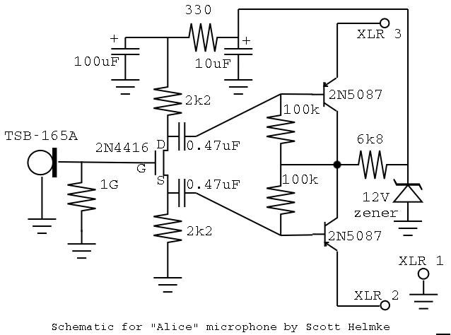
alice-schematic.jpg


There's just this nagging little problem of a slide switch on the outside of the mics.  Originally it turned the microphone off, but I'd like to do a low-cut instead for close-micing.

There are two places I could see having a low-cut, but I'm not sure which is best. The first is obviously to switch in a capacitor at the input (there's no input cap in the Alice mic), but I'm not really sure what's an effective value there given that the calculator's telling me that with the 1G gate resistor even 10pF is still below 20Hz. I know that the resistance there can't actually be 1G because a FET junction isn't that high, but I don't have a multimeter that could measure the actual impedance accurately to figure out a better number to use.

There's also the pair of 100K resistors forming high-pass filters with the 470nF caps. I was thinking I could switch a resistor in that goes across the two channels. My problem there is that, again, I need what seems like a super low value -- 22K -- to even approach a 20Hz cutoff! That's also losing some raw signal at all frequencies. I could compromise and use 47nF caps and 1M resistors with no change in bass response, then switch in a 100K and ... well, that's still only 34Hz, which is barely a dent in anything except the sound of the central heating.
 
I'm planning on shoving some Schoeps circuits into some cheapo BM800's i bought a few weeks back.

I drew inspiration from here: http://audioimprov.com/AudioImprov/Mics/Entries/2013/7/13_Searching_for_Bones.html

After a bit of fiddling around with component values in LTspice, i found some cap values for the one coming off the FET's drain, that would give me the cutoff frequency i wanted. As in, have a small cap for the high-passed "version" of the signal (in my case, 33nF turned out to be ok), and connect another, bigger value cap in parallel with it, for the "full range" option (220nF).
 
Khron said:
I'm planning on shoving some Schoeps circuits into some cheapo BM800's i bought a few weeks back.

I drew inspiration from here: http://audioimprov.com/AudioImprov/Mics/Entries/2013/7/13_Searching_for_Bones.html

After a bit of fiddling around with component values in LTspice, i found some cap values for the one coming off the FET's drain, that would give me the cutoff frequency i wanted. As in, have a small cap for the high-passed "version" of the signal (in my case, 33nF turned out to be ok), and connect another, bigger value cap in parallel with it, for the "full range" option (220nF).

Unfortunately, I'm not sure I can fit that whole circuit inside the cavity. There's actually surprisingly little room in there -- the switch itself takes up a lot of space.

I did realize that a pad would probably be the simplest thing to implement. If I can't figure out a good "input cap" value that provides an appreciable cut I think I'll just go with the pad.

Thanks for the ideas!
 
RuudNL said:
I did it once like this. (You can select the value of the 0.33uF 's to taste.)

Just out of curiousity ... couldn't you have just omitted the 1uFs and gotten basically the same effect?

FWIW, I tried a 100pF, shorted by the switch, at the input of the mic ... I can't really hear a difference, but it does read different on a recording in my DAW. Not very scientific. But it does suggest that the actual input impedance is a smaller number than I was anticipating.

My other option -- and one I know works -- is to wire in a pad instead.
 
Yes and no - by ommitting the 1uF ones, flipping the switch would've altered the DC biasing of the PNP's, i'd reckon :)
 
midwayfair said:
RuudNL said:
I did it once like this. (You can select the value of the 0.33uF 's to taste.)

Just out of curiousity ... couldn't you have just omitted the 1uFs and gotten basically the same effect?

FWIW, I tried a 100pF, shorted by the switch, at the input of the mic ... I can't really hear a difference, but it does read different on a recording in my DAW. Not very scientific. But it does suggest that the actual input impedance is a smaller number than I was anticipating.

My other option -- and one I know works -- is to wire in a pad instead.

You consider to use two additional capacitors, switch and two resistor, but the same effect you can achieve with only tow capacitors and one switch as i mentioned before...
You can use dpst switch also.
 
[ln76d], i'm pretty sure the OP's intention is to (re)use the SPST switch that's already built into the body of the dynamic mics he intends to "convert" into electrets ;) It's all there in the first two paragraphs of the first post...
 
[Khron] i think OP's can write for himself...
I don't know how the original circuit or the body looks (yes pictures are important!)  but probably make a substitution for spst with dpst isn't nothing complicated...
Most of dynamic microphones have slide switch and these usual have same size for spst, dpst, dpdt.
Where you see the problem?
 
I can only assume the main / original idea is to use as much as possible of the original mechanics, instead of spending who knows how long to find a substitute switch that fits in place of the original one :) If he was willing to replace the switch as well "anyway", i doubt he would've bothered opening a thread about it, in the first place :p

But i admit, part of this is speculation...
 
Sorry for the poor explanation on the mechanical part. The slide switch in the original mic is connected on the inside. it's a handheld dynamic, looks like a 58 with a switch on it. I don't have a way to remove the switch that's already there and definitely no way to reattach a new similar switch.

s-l225.jpg


Khron: I did consider the DC bias change, but my thought is that a. the transistors are just source followers (in fact I'm surprised they need to be matched) and b. they're matched anyway.

I'm going to try it on the next one; to test this one thoroughly I had to glue some things to the mounts, so it's a pain to mod this one more than a little bit. The two extra caps isn't really a problem, but it just requires some juggling on the layout.
 
Khron said:
I can only assume the main / original idea is to use as much as possible of the original mechanics, instead of spending who knows how long to find a substitute switch that fits in place of the original one :) If he was willing to replace the switch as well "anyway", i doubt he would've bothered opening a thread about it, in the first place :p

But i admit, part of this is speculation...

Yeah, the chinese use specail made for NASA, titanium-carbon, high quality switches...
 
midwayfair said:
Sorry for the poor explanation on the mechanical part. The slide switch in the original mic is connected on the inside. it's a handheld dynamic, looks like a 58 with a switch on it. I don't have a way to remove the switch that's already there and definitely no way to reattach a new similar switch.

You need only take off the plate and there will be one screw or two screws. Then you can normally solder wires to the switch, change switch or remove it completely and fit the circuit without any problem. Fold back from the hole side. After surgery, you can glue it.
Nothing speciall ;)
 
The plate is recessed, and I tried um ... forcibly removing it. It's bolted from the inside. I suspect that there are some VERY thin pliers or something involved. I've got four of these, and I haven't disassembled two of them, so I'll give it another shot.

Funny you mention gluing it ... I superglued the capsule to the rubber mount that originally held the dynamic coil! It was just about the perfect size. The 16mm ones are also the perfect size ... for the wrong side of the mount. Oh well. I'll have to find some other way of using those.

I confirmed that the 10K from base-to-base works. It's not super dramatic with the 220nF in there (cutoff is 72Hz) with voice, but it's actually more dramatic overall than I expected ... which of course makes sense because it's a -6dB cut on both sides, making it a -12dB/octave filter. Ran it through the DAW with a low (bass) tone on E to confirm my ears weren't playing tricks on me. I think I'll use 100nF caps next time, maybe tune things a little.
 
Sharp knife should be enough, you need fold back it from the center gap - where is the plastic slider.
Do you think that chinese manufacturers would make it so complicated?
 
ln76d said:
Sharp knife should be enough, you need fold back it from the center gap - where is the plastic slider.
Do you think that chinese manufacturers would make it so complicated?

Ahhhhh. Got it. Thank you!
 

Latest posts

Back
Top