


midwayfair
Well-known member
I hate it when this happens: I fix something but can't figure out why it was wrong int he first place and the fix doesn't make much sense.
I built a couple schoeps circuits on the same layout. I matched the transistors, resistors, everything that needed to be matched. One had some white noise and the other was perfectly silent. The signal output was the same on both.
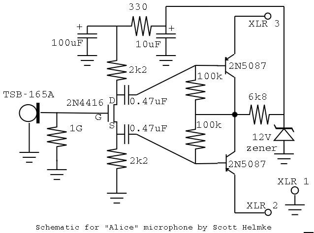
[EDIT: All the changes I made: I added a 47R+22nF LPF to the output (pretty common, I think); I used 2K7 instead of 2K4 for the source and drain resistors; there is now a 220nF from the base of Q2 to the +12V regulated; and there is a switch to put a 10K from the base of Q2 to the base of Q3 (but the white noise was identical in both switch positions). Also, the transistors I left in are 2N4403, which are low-noise types.]
I tracked the noise down to the base of the PNP that follows the drain output.
I rechecked all my components, replaced all of the transistors (I tried pairs of multiple transistor types -- incl. 3906, 4403, and BC328/338), and even used a socket to audition transistors that weren't matched.
In the end, the only thing I could find that would kill the while noise was putting a cap from the base of that transistor to ground or the power rail, i.e., creating a low-pass filter in only one band. I used 220nF -- it was the smallest I could go to get the second mic down to comparable noise levels.
This ought to unbalance the output, which should give me MORE noise I would think. It should also screw up the frequency contentbut I ran it through my DAW and a frequency analyzer with a banjo and compared with the other mic. I get approximately the same content as far up as 17KHz, beyond which the banjo isn't really registering.
The only thing I can think of is that somehow I ended up with more gain on the upper band, and the filter on that band brought the total gain back down to identical levels.
EDIT: a little more experimentation ... I was able to get the other mic a little quieter doing the same thing ... specifically, though, it's the cap from the base of the upper transistor to the +12V power rail that's the absolute quietest operation -- not the collector (which is the "upside down ground") and not circuit/chassis ground. Connecting the lower (source-output) base makes the noise worse. So maybe something about this version of the circuit is NOT balanced and requires a correction.?
I built a couple schoeps circuits on the same layout. I matched the transistors, resistors, everything that needed to be matched. One had some white noise and the other was perfectly silent. The signal output was the same on both.
[EDIT: All the changes I made: I added a 47R+22nF LPF to the output (pretty common, I think); I used 2K7 instead of 2K4 for the source and drain resistors; there is now a 220nF from the base of Q2 to the +12V regulated; and there is a switch to put a 10K from the base of Q2 to the base of Q3 (but the white noise was identical in both switch positions). Also, the transistors I left in are 2N4403, which are low-noise types.]
I tracked the noise down to the base of the PNP that follows the drain output.
I rechecked all my components, replaced all of the transistors (I tried pairs of multiple transistor types -- incl. 3906, 4403, and BC328/338), and even used a socket to audition transistors that weren't matched.
In the end, the only thing I could find that would kill the while noise was putting a cap from the base of that transistor to ground or the power rail, i.e., creating a low-pass filter in only one band. I used 220nF -- it was the smallest I could go to get the second mic down to comparable noise levels.
This ought to unbalance the output, which should give me MORE noise I would think. It should also screw up the frequency contentbut I ran it through my DAW and a frequency analyzer with a banjo and compared with the other mic. I get approximately the same content as far up as 17KHz, beyond which the banjo isn't really registering.
The only thing I can think of is that somehow I ended up with more gain on the upper band, and the filter on that band brought the total gain back down to identical levels.
EDIT: a little more experimentation ... I was able to get the other mic a little quieter doing the same thing ... specifically, though, it's the cap from the base of the upper transistor to the +12V power rail that's the absolute quietest operation -- not the collector (which is the "upside down ground") and not circuit/chassis ground. Connecting the lower (source-output) base makes the noise worse. So maybe something about this version of the circuit is NOT balanced and requires a correction.?