You are using an out of date browser. It may not display this or other websites correctly.
You should upgrade or use an alternative browser.
You should upgrade or use an alternative browser.
Lang PEQ-2A clone...RESURRECTED
- Thread starter damnyankee
- Start date
Help Support GroupDIY Audio Forum:
This site may earn a commission from merchant affiliate
links, including eBay, Amazon, and others.
damnyankee
Well-known member
I planned on uploading/posting the fax he sent me when I go back to work. I don't have a scanner at home and you wouldn't be happy with an 8mp photo of a fax.
damnyankee
Well-known member
Yep - both coils are triple tapped with values. Even the Caps are numbered CO, C1, C2, C3, etc and includes their values - and not only are the caps matched to the coils, but also includes the colored wires which apparently go out to the various pots.
I will go get the images scanned later tonight and post them because I know there are at least two of the guys on GroupDIY in the last couple years that were having issues with their High Freq cans - so hopefully this info will help them with their repairs.
Haven't heard back from Abe/AC Sound Studios to see if he'd be up to spearheading the Lang build. If the cans from ETC/Freed are too expensive, maybe ETC/Freed can do the coils instead (speaking of which, isn't there someone in here who can make these triple tapped coils for us?)
The pcb should be an easy build and Dan/Collective Cases already did the front panel.
mitsos
Well-known member
- Joined
- May 4, 2007
- Messages
- 2,886
You should be able to build this on any of the pultec builds, or even directly on the switches if you want. I had done a lang amp layout, but never tried it out, cuz I never got it working properly in spice back then. I think there was an issue with spice. I can help with a layout, time permitting. I haven't seen the front panel layout, do you have a link/image?
The inductors are no problem if they're ferrite cores, if you want toroids it's a bit more trouble but I can possibly help with those depending on the info in the notes.
The inductors are no problem if they're ferrite cores, if you want toroids it's a bit more trouble but I can possibly help with those depending on the info in the notes.
damnyankee
Well-known member
That's good you could possibly help with layout and the coils if ETC/Freed can't do them.
As for the front panel - we can ask Dan. I recall being blown away when he showed Abe & I what he came up with: it looked identical to the PEQ-2 panel. It was best quality work.
As for the front panel - we can ask Dan. I recall being blown away when he showed Abe & I what he came up with: it looked identical to the PEQ-2 panel. It was best quality work.
damnyankee
Well-known member
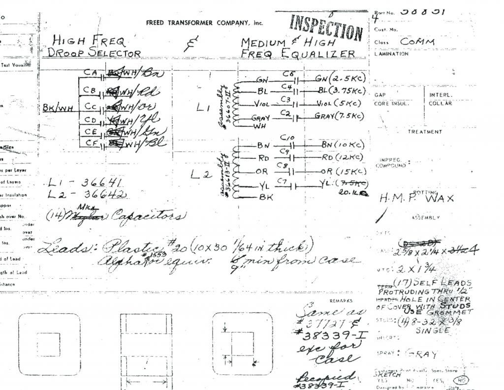
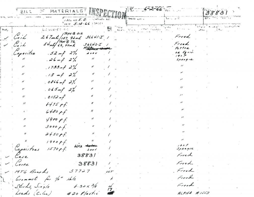
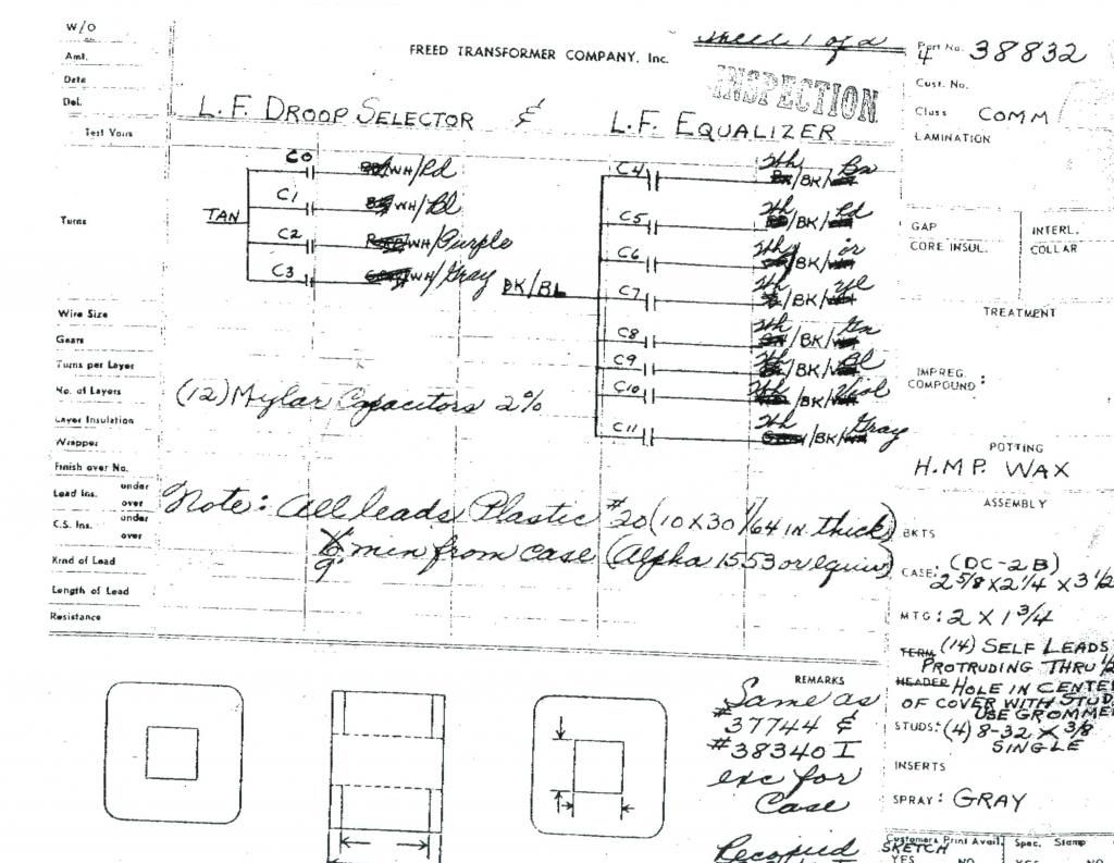
Ok...the moment you've been waiting for...*drum roll please....* the Lang Filter Networks!!!
#38831 Medium & High Frequency Filter Network
#38832 Low Frequency Filter Network
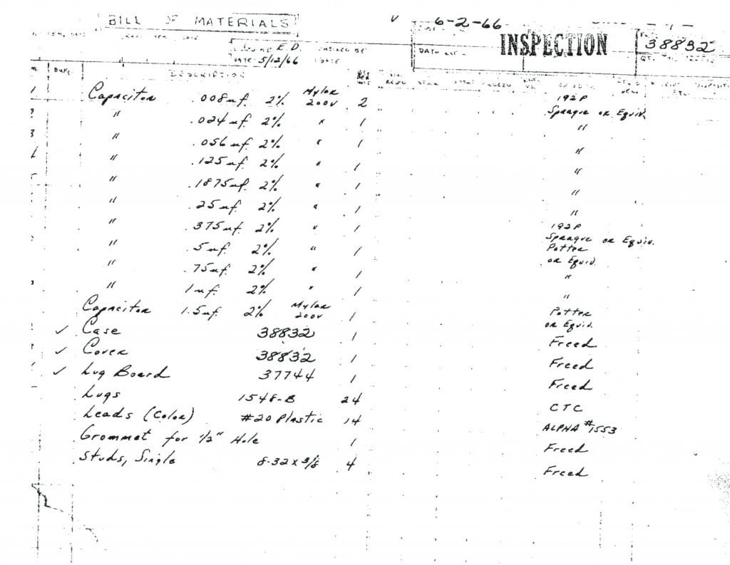
Abe/AC Sound offered to check into doing the pcb (with a little help from us friends of course). Coils may be an issue but I think ETC/Freed may be able to do them if they can't do the cans themselves.
Is anyone fired up yet???
#38831 Medium & High Frequency Filter Network


#38832 Low Frequency Filter Network


Abe/AC Sound offered to check into doing the pcb (with a little help from us friends of course). Coils may be an issue but I think ETC/Freed may be able to do them if they can't do the cans themselves.
Is anyone fired up yet???
ruairioflaherty
Well-known member
Very very cool detective work! Props for your persistence and honesty in sharing (rather than sitting on the info).
Well done.
Well done.
creal
Well-known member
very nice investigation damnyankee.
 ;D
;D
damnyankee
Well-known member
;D
Any suggestions on how to put these things together on a pcb?
Any suggestions on how to put these things together on a pcb?
Great work Yankee!
mitsos
Well-known member
- Joined
- May 4, 2007
- Messages
- 2,886
Thanks for posting that.
It'd be nice to confirm what that red resistor is behind the 620R on the connector, in the pics Mark posted a few pages back, as well as confirm where they connect to for sure.
As for a PCB, if it were tied to a faceplate design, it would be nice to see one that is parallel to the faceplate, so all controls could be soldered directly to the PCB, and the whole EQ would just fit into the faceplate, leaving the only wiring for the trafos/XLRs and PSU.
damnyankee
Well-known member
Face plate design would be great...and making a stereo or multi-channel unit would be even better.
I'm sure Mark would be willing to ID that - are you referring to the red resistor mounted on the blue lug behind the 620 Ohms 5% carbon resistor?
I'm sure Mark would be willing to ID that - are you referring to the red resistor mounted on the blue lug behind the 620 Ohms 5% carbon resistor?
creal
Well-known member
Hi all,
Here is the front panel i designed last year.
It was made by Frank @ NRG.
Just rename the PDF as fpd
I suppose the 620r is the loaded resistor for the input TX.
I made the amp of my units in vero board but i started to play with eagle for the PSU/true Bypass/Amp.
For the first unit, i used the original psu schematic with a 2x18 30va.
For the seconde unit, i change the PSU and replace the old one by a LM317 based and a 7805 for the relay.
I'll post the Eagle file after updates with the 317...
Other question about the LF section. (#38832 Low Frequency Filter Network)
The schematic shown 12 caps for the droop and the boost but i just read 11 value in the BOM?
someone have an idea about that?

http://www.twin-x.com/groupdiy/albums/userpics/Cyril_PEQ-6.pdf
Here is the front panel i designed last year.
It was made by Frank @ NRG.
Just rename the PDF as fpd
mitsos said:Thanks for posting that.
It'd be nice to confirm what that red resistor is behind the 620R on the connector, in the pics Mark posted a few pages back, as well as confirm where they connect to for sure.
As for a PCB, if it were tied to a faceplate design, it would be nice to see one that is parallel to the faceplate, so all controls could be soldered directly to the PCB, and the whole EQ would just fit into the faceplate, leaving the only wiring for the trafos/XLRs and PSU.
I suppose the 620r is the loaded resistor for the input TX.
I made the amp of my units in vero board but i started to play with eagle for the PSU/true Bypass/Amp.
For the first unit, i used the original psu schematic with a 2x18 30va.
For the seconde unit, i change the PSU and replace the old one by a LM317 based and a 7805 for the relay.
I'll post the Eagle file after updates with the 317...
Other question about the LF section. (#38832 Low Frequency Filter Network)
The schematic shown 12 caps for the droop and the boost but i just read 11 value in the BOM?
someone have an idea about that?

http://www.twin-x.com/groupdiy/albums/userpics/Cyril_PEQ-6.pdf
Biasrocks
Well-known member
Reviewing the pictures, it looks like it attaches to the black wire and then the white wire along with the 620R.
I'll pull the Lang out in the next few days and confirm the connections and value.
Mark
I'll pull the Lang out in the next few days and confirm the connections and value.
Mark
mitsos said:It'd be nice to confirm what that red resistor is behind the 620R on the connector, in the pics Mark posted a few pages back, as well as confirm where they connect to for sure.
mitsos
Well-known member
- Joined
- May 4, 2007
- Messages
- 2,886
Thanks Mark. There are 2x 620R in your lang. One is directly on one of the trafos (the input, presumably), the other is at the connector. I attached a pic of the amp pcb with the pins marked for easier deciphering. I don't know if it was me who mirrored the trace side or if I got it that way, but I know I used it when I tried to get this amp working ages ago. I added the pin numbers/functions. Anyway, looking at the connector pics(I just saw there are two pics of it), it looks like both resistors connect to the amp input, with the 620R then going to pin H (gain pot) and the red resistor going to ground. Anyway, the red might be a load R for the amp, but now I'm curious about the 620. An in-focus pic of the connector would be excellent.
Also, looking at the low switches, there looks to be a resistor between them? Can you confirm?
To me, it looks like the signal go into the filter like it does in the pultec, from the trafo to the Hiboost pot. But the pultec has both ends of the pot connected but it's hard to tell if this has pin 1 connected or not.
Attachments
damnyankee
Well-known member
creal wrote:
"Other question about the LF section. (#38832 Low Frequency Filter Network)
The schematic shown 12 caps for the droop and the boost but i just read 11 value in the BOM?
someone have an idea about that?"
You are correct. The BOM lists C1 as two (2) mylar caps that are .008uF 2% 200V. Looking at the L.F. Droop Selector, I am assuming they are C0 and C1 because there isn't a C0 on the BOM.
I've been in Google Books reading up old books. The authors claim the sound of inductor-based eqs come from the ferrite cores and taps. If this is true, this begs the question: is there anyone who can recreate these two coils?
damnyankee
Well-known member
And Creal - my apologies for not giving you the nod for the panels.  I thought Dan came up with that!
damnyankee
Well-known member
*crickets*
abechap024
Well-known member
Well guess what just blew through the shop?
fixing a pair of these for a friend.
Initial thoughts? They are HEAVY.
Tone monsters in a surprisingly subtle way. I wonder how much of the tone comes from the huge transformers?
Anyway stuck on one of the amplifier cards not passing signal...
excited about these...
fixing a pair of these for a friend.
Initial thoughts? They are HEAVY.
Tone monsters in a surprisingly subtle way. I wonder how much of the tone comes from the huge transformers?
Anyway stuck on one of the amplifier cards not passing signal...
excited about these...
Similar threads
- Replies
- 7
- Views
- 935
- Replies
- 1
- Views
- 875
- Replies
- 0
- Views
- 513


