LED VU Rectifier Schematic

GroupDIY Audio Forum

Help Support GroupDIY Audio Forum:

This site may earn a commission from merchant affiliate links, including eBay, Amazon, and others.

conleycd

Well-known member
Joined
Aug 9, 2007
Messages
213
Well I have plagiarized a handful of circuits to make a LED board that I think is really adaptable and usable for a variety of monitoring needs.

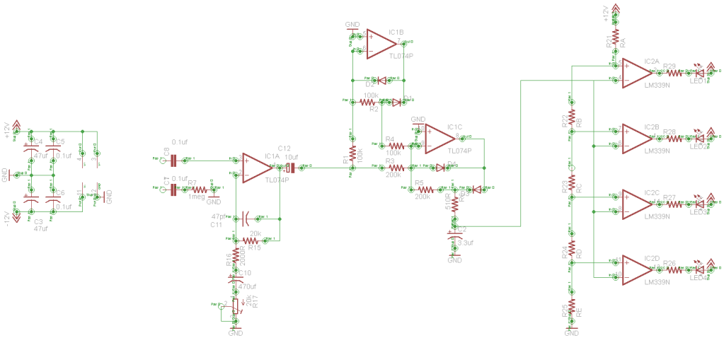
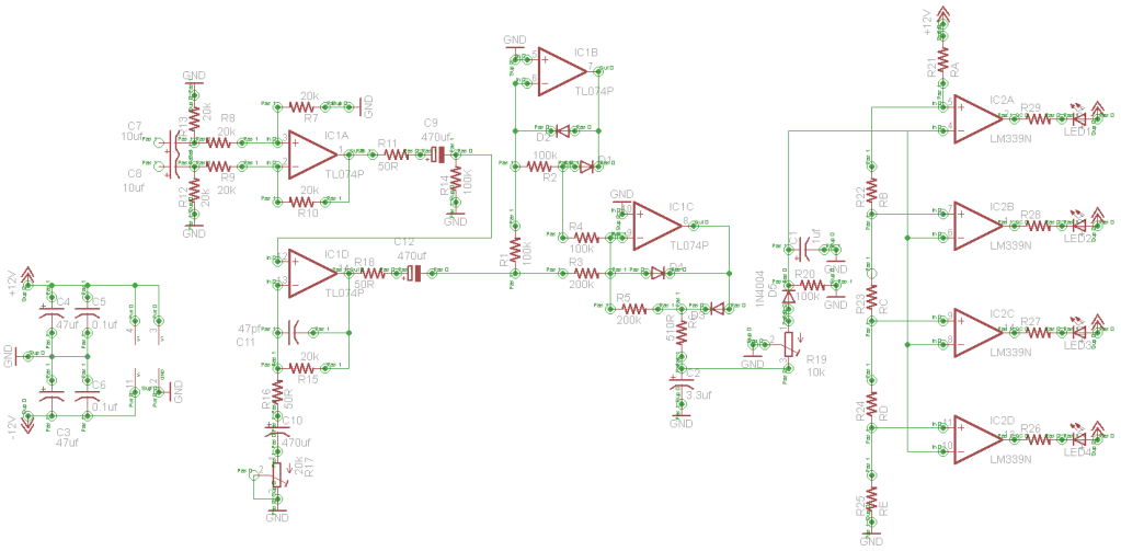
In essence, it starts off with a balanced line receiver (which could be easily adapted to an unbalanced buffer) which then runs into an OPAMP that allows for gain.  These are pretty standard circuits.

After this the signal hits a Precision Full-Wave Peak Detector [from p.9 of the LM3916 datasheet].

Then to the quad comparator LM339 LED schematic that I lifted from somewhere.  I have left the values off for the resistors in this schematic - not just because I don't necessarily know them but also because these will vary depending on what people want each LED to correspond to.

I suspect that there are some redundant parts - perhaps some blatant errors.

Assuming my board layout is reasonable... I think this could be a useful project for many DIY projects. 

I wanted to check in with people to make sure I was on the right course and also if there were any errors.

VURecto.png


CC
 
Since designing LED meters has been one of my areas of interest for a few decades now, yes, you are using way more parts than necessary. LED meters are usually designed with a sharp pencil for low cost, and current consumption... 

With the 339 open collector you could string the leds in series and save some current.  Way too many DC blocking caps.

Your signal looks like it dead ends at R19.

You probably don't need all those steering diodes in IC1C.

Chop chop chop... there will still be a meter left... without the spare parts.

JR
 
Teach me wise one!  I am but a padawan learner.

R19 is supposed to be a potentiometer to attenuate the signal into the LM339 circuit.  It looks like I grounded the wrong end (output should be from the centre pole) and one side grounded.

Should I loose all the blocking caps?  This whole thing is really supposed to be able to hang on the end of a microphone preamp, sub bus, or whatever... So is C7 and C8 necessary or should I run straight into the resistors?  Keep C9 but drop C12 or vice-versa?

The entire circuit of IC1B and IC1C are straight copies from the datasheet of LM3916 (less any accidental errors).

Do you have schematic (not for production use or anything) worth sharing that I could jig up a board on?  I did this up because there were few circuits that incorporated a "precision" rectifier and also had a balanced (or unbalanced) buffer to hang off of an output without causing problems down the road for some other receiving input device.

Thanks.

CC
 
A couple ideas would be:
You could use the debalancing amp as your signal booster and drop the booster amp section entirely. Follow the debalancer with a pot to trim the meter level. The coupling cap is probably not needed (certainly could be smaller).

The diodes should stay for full wave peak det. but with a little cleverness in layout, you can optionally make it average detector.

All the stuff between C2 and the 339's is unneeded (actually detrimental - it's loading your timing cap). Cuz you have it, I would use the extra opamp (IC1D) as a follower after  C2.


Or:

this is a really good job for a microcontroller...
 
conleycd said:
Teach me wise one!  I am but a padawan learner.
I don't want to design one for you, since you could just copy somebody else already, and I don't feel like designing yet another LED meter using old time circuitry.

I will be more specific in my critique, for academic purposes.
R19 is supposed to be a potentiometer to attenuate the signal into the LM339 circuit.  It looks like I grounded the wrong end (output should be from the centre pole) and one side grounded.
Lots of trim pots... ?  Meters with gain trims kind of defeats the purpose of a meter.. 5% resistors should get you to a fraction of a dB with known rail voltages.  Only mechanical VU meters with less that 1 dB resolution, due to how they work, might benefit from a fine gain trim..

A 4-LED meter is not expected to deliver ultra precision. 
Should I loose all the blocking caps?  This whole thing is really supposed to be able to hang on the end of a microphone preamp, sub bus, or whatever... So is C7 and C8 necessary or should I run straight into the resistors?  Keep C9 but drop C12 or vice-versa?
What is the resolution of your lowest LED? If you are only reading -20dB down, DC offsets and ground hum will not register on the meter. You may not need a gain stage either.
The entire circuit of IC1B and IC1C are straight copies from the datasheet of LM3916 (less any accidental errors).
And National Semi makes more money by selling you more opamps...

The first stage IC1B is a common full wave rectifier. This will make a meter more accurate in theory but in practice, you will rarely notice a difference between full wave and half wave for slow average readings. Peak is another matter where a peak may be significantly different in both directions.

the second stage (IC1C) while it looks the same is actually doing something different, established a different attack and release time constant.  This is useful for peak reading meter, not as much for average (which VU meters generally are).

The pot and diode, and stuff is not serving any useful purpose I can thing of, and voltage drop from the diode will not be very well behaved.
Do you have schematic (not for production use or anything) worth sharing that I could jig up a board on? 
nah... I haven't designed something like that... in a few decades.  These days I use a small micro which when you count the labor of installing all those parts can be cost effective.

And it allows you to do many tricks, you can't in crude analog.
I did this up because there were few circuits that incorporated a "precision" rectifier and also had a balanced (or unbalanced) buffer to hang off of an output without causing problems down the road for some other receiving input device.
You can make the input present a balanced (impedance) load to the outside world without actually being balanced. it just needs to be the same impedance to + and - inputs. 

Thanks.

CC
 
Before reviewing John's wise comments, snap-jabs:

R12 R13 do no good.

R11 R18 not needed.

I don't like this common input stage, the impedances are whack. The impedance-sin is lessened if resistances are scaled higher; with TL074 you could go 1Meg all around. Hiss rises, but no so it reads on a so-called "VU" meter. This also allows small film caps instead of polar electrolytics.

C9 should not be needed (if next point is addressed).

R16 is absurdly small: TL074 won't cover the audio band at gain of 20,000/50= 400, you can't trim R17 20K trimmer to 50 ohm resolution. 10:1 range makes sense; 400:1 does not.

That sure is a lot of diodes; I'm not grasping why two precision rectifiers followed by a NON-precision peak-catcher. IC1C seems to do well what D5 does poorly.

R19 wiper sure should not be grounded. I assume R19 is an attack RHEOSTAT, not a potentiometer.

> quad comparator LM339 LED ...  I have left the values off for the resistors

But that's the important part. If LED4 is -60VU you need a PRECISION rectifier; if it is -10VU you can 1N914 it.

Neve did much of this, plus >30dB quasi-LOG, in 1/10th the transistors of a TL074.
http://i53.tinypic.com/245jy55.jpg
 
You don't need R19, D5 or C1.  They are modifying the response of the precision peak detector from the datasheet. You probably don't need R20 either.

-Jack


Attachments

  • peak.gif
    peak.gif
    22.5 KB
Ok...  without reposting the revised schematic just yet or scrapping the whole thing...

My thought behind this is to offer myself (and others) some flexibility in what scale/LEDs lit they want to use.  So that was my thought regarding gain and the input attenuation (although I guess I could scrap the input attenuation if the resistors were scaled appropriately for the LM339 portion).

Instead of a balanced receiver - what if I go stock unbalanced with a 0.1uf or 1uf cap on the non-inverting opamp input (1meg or so impedance) and have this opamp also add gain as needed?  If used on a balanced output should I tie a 1 meg resistor on the "-" output to tied to "ground?"  Should R16 then be 2k if the pot is 20k?  

I have no sweet clue what is fully occurring besides "Precision Full Wave Peak Rectification" - per the datasheet.

R16 is incorrect (if it is kept) - it the output should be from the centre of the pot with the non-input side grounded.

I'll eliminate the stuff before the LM339 circuit.  I think this stuff may have been to connect the circuit to a speaker output?

I had half intended to to select the resistor values based on trial and error with a handful of different scale points for clipping and for initial indication.  I'd like to be able to see a ground loop hum on the first indicator LED (but that's for my personal preference).  If other people are using the board or circuit they may want to see a -10vu.  Granted... having 2 opamps doing unnecessary stuff is a current draw and increases the complexity of the board and problems...

CC
 
JohnRoberts said:
Since designing LED meters has been one of my areas of interest for a few decades now, yes, you are using way more parts than necessary. LED meters are usually designed with a sharp pencil for low cost, and current consumption... 
There seems to be a glaring hole in the market for decent LED bargraph drivers. The hoary old LM391x devices have been around for ever and there must be room for improvement (onboard rectifier etc). There must be a reason that most mixer manufacturers resort to strings of LM339s and resistors (mind you 339s are awfully cheap so that may have something to do with it). Sanyo, Rohm etc seem to make a few goodies but finding data & comparison tables is hard and finding the chips is harder.
Seem to find myself resorting to small PICs with onboard A/Ds but these are limited to parallel drive (oh for a high voltage open collector PIC !).
M
 
It is hard to justify dedicated analog silicon when you can use a cheap standard micro that is far more flexible...

I have payed around with the idea of selling some pre-burned PICs that use a few select lines so you could field select between a handful of different generic meters by shorting or floating a few input pins, but I am not interested in re-entering the kit business, and  real manufacturers have enough unique needs that they are better off with custom software.

JR

 
You wouldn't have to really re-enter the kit business. I bet one of the forum's micro-vendors would love to work out some sort of deal with you. They can handle all that stuff.
 
Look... I'd buy a reasonable kit.

Here's my rework guys.  I think I've incorporated most suggestions.  I'm not sure if I need a pull down resistor after the buffer/gain amplifier (after C12).  I revised R16 (is this setting minimum gain?)

There is a spare opamp on the TL074.  Is there a place for it reasonably?

VUrevised1.png


CC
 

Latest posts

Back
Top