Lightweight guitar amp ideas... Now with compactron! (and schematic, more ?s)

GroupDIY Audio Forum

Help Support GroupDIY Audio Forum:

This site may earn a commission from merchant affiliate links, including eBay, Amazon, and others.
lassoharp said:
How much safety margin should I allow when calculating heater current capacity?  Current draw from a 6.3V bayonet base lamp, plus a 6C10 plus a 6DZ7, plus what percentage of that total for safety?  50%?  100%?

AC are heaters normally ran at full rated load so that final voltage will be as close to spec as possible.
You will likely run a little higher than 6.3V @ 50% and this will probably differ slightly from transformer to transformer.  If winding is rated 6.3V @ 2A, run at 2A, you will be fine.

The HT winding is often ran at 50% or less just so the transformer runs cool.

Great info, thanks.  I've still gotta figure out what I need to do for a PT.  Might have to get one custom spec'd so it can be as light as is practical.

For the OT, I found out that Dave Allen sells a Heyboer transformer designed for 2x EL84 or 2x 6V6.  It's designed as a better-sounding replacement for the puny transformer that comes stock on the Pro Junior, Blues Junior, Princeton Reverb, etc.  The only drag is that it weighs 1.5 lbs as opposed to about 15 oz. for the smaller-core Pro Junior transformer.  I think that's just a tradeoff I'm going to have to make... about half a pound is something I can live with for perhaps a touch of headroom and cleaner bass when cranked.  The other upside is that it's about $50 for a quality, USA-made product with high-grade steel.  Yes, there are cheaper transformers but for something that nice, it's a fair price.

This is starting to come together nicely in my head.  I'm hoping I can make this a reality sooner-than-later.

 
Soapbox, I like your moxie, and I've run down the lightweight thingy here on this board myself.  The weight is not in the tubes, but the iron.  You might buy yourself some weight savings by going toroidal for the PT.  Might.

As for the 6DZ7, played around with those myself a few years back.  Like a 7189?  No, closer to a pair of 6BQ5, and even closer to 6AQ5s.  These were never widely used and thus never had the design rigors/demands placed on them for reliable production.  Not a heavy hitter and the screens have a glass jaw.  I would say anything over 350 VDC is asking for arcing.  Maybe more resistance on your screen supply to play it safe, at least 1K.
 
Thanks for that.  1K on the screens is where I'll start, then, and I'll run the plates down to 350V for a start. I had considered a toroidal PT, but have shied away from it because I've heard from many that they don't like what it does in a guitar amp under high demands.  I'm familiar with the sagging of a too-small EI PT in a guitar amp, and that's something I actually kind of like the character of.  But I have no first-hand experience, so I'm basically working under a lot of assumptions from talking to people who have been down some of these roads before.

 
lassoharp said:
Also keep us posted on how the paulownia wood cab works out.  Custom work here?

Yep.  Got a quote from Mather Cabs in nashville.  They've built cabs for me before.  Excellent to work with, and hands-down the best cabinets I've ever seen.
 
Plates aren't your weak spot: the screens are, so I suggest having max ~350 on the screens, let your plates do what they do.

And I never heard of paulowina...I went with cypress: lighter and stronger than pine, and cheaper here too, whoda thunk?
 
schmidlin said:
Plates aren't your weak spot: the screens are, so I suggest having max ~350 on the screens, let your plates do what they do.

Ah!  Gotcha.

And I never heard of paulowina...I went with cypress: lighter and stronger than pine, and cheaper here too, whoda thunk?

Paulownia is also known as Japanese Princess Wood.  Some people use it to make guitars out of... it's super light weight (just barely lighter than balsa and nearly as strong as pine).  I hear it's become popular recently as a wood to make wooden surfboards out of, due to its weight-to-strength ratio.

The one caveat I've heard is that it doesn't always like to hold screws as well as pine.  I'm planning on wicking water-thin CA glue down into the threads to strengthen all screw holes, but that's a bridge I'll cross when I come to it.
 
Took another glance at the 6DZ7 data sheet and it says V(a) max is 440v, while V(g2) max is only 300v.  Perhaps I can get away with running a little hotter on the screens, but I will definitely keep it below 350 as you suggested... I might set a target of about 325 if I can get there.
 
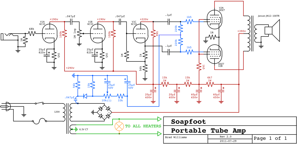
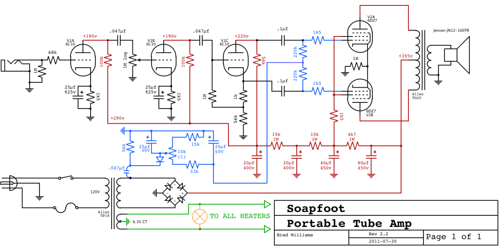
OK, here's my version 2.0 schematic.  I've made some tweaks as per conversation above, and some other changes--the most drastic of which is the bias supply. 

Rather than trying to source a transformer with a C- tap, I borrowed a page from the Pro Junior's book and took a reduced voltage from half of the bridge rectifier, then half-wave rectified that again and divided it down further.  This is nearly a direct rip of the Pro Junior/Blues Junior bias supply, except I increased the filtering a bit and made it adjustable by adding a 10k trimmer (as per the Bill M mod of that circuit).  Values are estimated as of right now... I'd have to tweak that or do some more math once I know exactly what my voltages will be... will probably be most convenient just to breadboard it.  The reason I went this direction is that, while it increases my parts count slightly (by a couple of caps and a resistor or two), it increases my chances of being able to find a suitable 'stock' PT.  In fact, the Pro Junior PT would work, and is light (though I wish the HT secondary had a few more turns on it... output is only 319V).

I also added a 1 ohm resistor to the cathodes of the 6DZ7 as a bias test point.

Tiny_Amp_20.png


Any thoughts, warnings, or opinions?
 
Good gawd, this turning into a trainwreck.  Not dissing you soapbox, but how you drew up the new bias supply is counter-standard: hard to read, IMHO.  Damn those bridge circuits combined with bias supplies.  Just rip-off an Ampeg B-4 or go cathode.  Sheesh.

Well done PRR, as usual.
 
schmidlin said:
Good gawd, this turning into a trainwreck.  Not dissing you soapbox, but how you drew up the new bias supply is counter-standard: hard to read, IMHO.

To tell the honest truth, I really don't know what proper standard/procedure is. I'm entirely self-taught from asking questions on internet fora and reading a few books. I make no claim to be anything other than a tinker/hack. I'm always interested in learning, but learning sometimes requires making mistakes, which I still do... a lot.  My two college degrees are both in music--I've never had even a single course in electronics. Whatever I've been able to piece together is just from blindly stabbing around in the dark. I realize this can be hard to watch for someone with real training and expertise, but all I can do is apologize for my ignorance, and hope that someone will help enlighten me.

Damn those bridge circuits combined with bias supplies.  Just rip-off an Ampeg B-4 or go cathode.  Sheesh.

What I was doing was ripping off a pro junior. I could go cathode... I had thought about it. I had hoped to get as much power/headroom as I could, however... this was my motivation for wanting to go fixed. I've never seen an Ampeg B-4.  I'll look that up.
 
To tell the honest truth, I really don't know what proper standard/procedure is. I'm entirely self-taught from asking questions on internet fora and reading a few books. I make no claim to be anything other than a tinker/hack. I'm always interested in learning, but learning sometimes requires making mistakes, which I still do... a lot.  My two college degrees are both in music--I've never had even a single course in electronics. Whatever I've been able to piece together is just from blindly stabbing around in the dark. I realize this can be hard to watch for someone with real training and expertise, but all I can do is apologize for my ignorance, and hope that someone will help enlighten me.


I would advise putting together some sort of bench test setup for doing trial runs.  Great way to learn and avoid later grief & smoke.
 
Sorry for getting snarky with you, soapfoot: we all learn at our own pace/style. 

I meant the Ampeg V4(B):
http://www.webphix.com/schematic%20heaven/www.schematicheaven.com/ampegamps/v4bpowramp.pdf

Note it's linear layout for the bias supply.  Just much easier for my moldy brain to wrap it's head around.  Vary the 75K to get the voltage you need, or use a voltage divider at the end.  You could simplify this more by ditching the 10K and (2) 10uf caps and just go with a single larger cap, say 47uf.

Best.
 
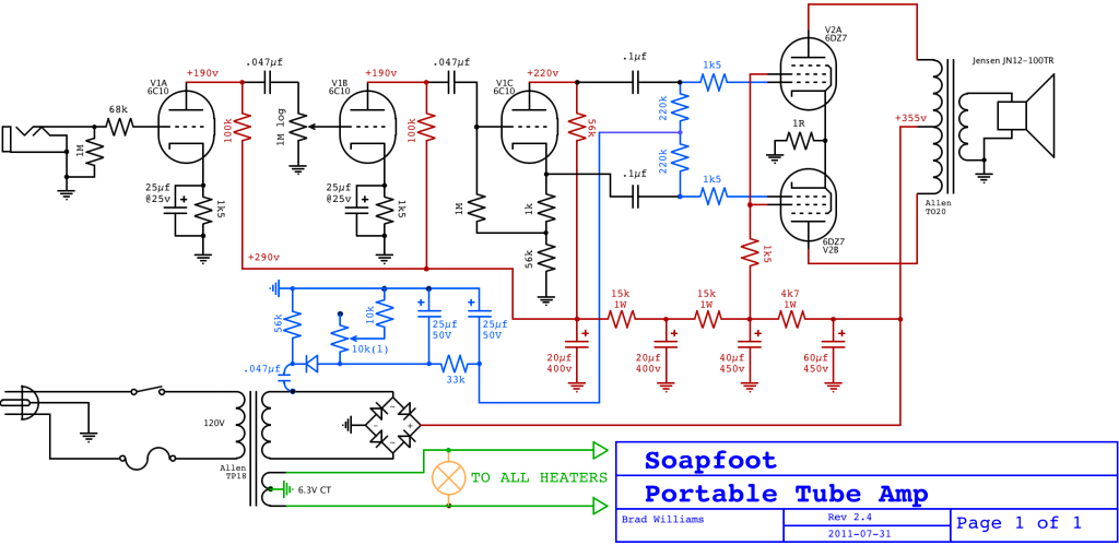
OK-- Looking at the stock Pro Junior schematic, it's the exact same scheme as the V4-B, but with some value changes to reflect the much lower bias voltage of the 6BQ5.  I put a rheostat in series with the resistor that you suggested to vary the voltage.

Is this better?

tiny_amp_24.png


I have some other questions about my design which I'll get to in a minute.  I'm concerned that the first stage might overload the second, so looking at the transfer characteristics of some tubes I came up with an idea.  I'll draw it up and wait for people to tell me why it won't work (I'll duck to avoid the tomatoes!)
 
Since you already have an amp that is what you want, but too heavy, what if you put that head in the lightweight wood cab with the Neo speaker, how much weight would you save?
 
Back
Top