Lomo 19a19 TubeMic Power Supply

GroupDIY Audio Forum

Help Support GroupDIY Audio Forum:

This site may earn a commission from merchant affiliate links, including eBay, Amazon, and others.

geebeeVIE

Member
Joined
Jan 23, 2015
Messages
22
Hi Folks,

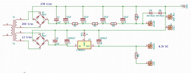
I bought a Lomo 19a19 Microphone, one of the "butchered" kind, which has the most  horrible selfmade power supply I ever saw. This PS is delivering 6,0 and 90 V to the microphone.

I also have a chinese power supply, which is quite a simple circuit, however I am a noob when it comes to electricity.
I am already proud that I managed to trace the circuit (hopefully correctly....)

So I want to modify it to generate the voltages I need.
The heater can stay as it is, as it is perfectly matching the specification of the 6231B-R tube.

However, I need to get the anode voltage down.

I am considering the following:

Replace R1 and R2 with 100k  resistor, 0,25W
Replace R3 with 100k variable resistor, 0,25W
Replace C2 - C4 with 100uF/250V

Am I halfway in the right ballpark?

I think the two Zeners - rated at 75V each, should provide some kind of protection. Should they be replaced as well?


The two zeners look to me like they are shunt regulating the supply to 150V. To change the voltage to 90V you need to replace them with a pair of zeners that total 90V. You may need to increase R1, R2 and R3 a little to ensure the correct current flows through the zeners but certainly not to 100K. Increasing the values of the smoothing caps is a good idea.

Cheers

Ian
 
So I've done some research on these mics because I've wanted to DIY one.
From what I've read, there are a few mic variations that need different PSU  (there are several good threads on 19A19 here on Groupdiy - use the search)

The tube version that it sounds like you have needs 90v for B+ and ~6.0v for heaters.

You say that the PSU "is delivering 6,0 and 90 V to the microphone" but that "I need to get the anode voltage down. "
What is the B+ voltage you are aiming for? And why?

I have an orphan Lomo PSU if you need any info from it.
 
Also, please make your thread titles specific - you'll get better help (i.e. "Lomo 19A19 tube mic PSU")

Your schematic has two R4 and no R3.

If Zeners are setting the B+ as Ruffrecords assumed, it is not a good way to set the B+ voltage in a tube mic. Zener's are thought to generate noise. It would be better to use a PSU like the original Lomo where the Resistances set the correct voltage with the load connected. Estimating the current draw of the mic makes resistor selection easy using Ohm's law.
 
C2 can NOT be 250V rating, there's 278V there. And on C3 C4 when the mike is not connected (and Zeners omitted). These may all be 300V rating for light use, 400V for serious work.

100K is surely wrong.

You need to know the *current* the mike sucks. As well as the voltage.

You seem to have 278V on tap and want to get to 90V. You need to lose 278V-90V= 188V. Since you have three drop resistors, each one should drop 188V/3= 62V.

Taking a very-wild-guess of 2mA suckage, 62V/2mA is 31K Ohms each resistor. A hungry 10mA mike would be three 6.2K resistors.

That Zener-thing at the end is *probably* not intended to be active in normal operation, making its hiss moot. The supply output voltage should be around 90V when the mike is connected, but what if it is disconnected or goes dark? The output soars to >270V. In fact this will happen at every cold turn-on. The 150V Zeners limit this rise, then drop-out as the mike begins to suck-down toward 90V.

I believe three stages of 6.2K+22uFd filtering, ~~40dB/stage, gives enough ripple filtering. 47uFd is not wrong either, but parasitic resistance means 47 is not twice 22. If it truly buzzes, use more R-C stages.
 
dmp said:
So I've done some research on these mics because I've wanted to DIY one.
From what I've read, there are a few mic variations that need different PSU  (there are several good threads on 19A19 here on Groupdiy - use the search)

The tube version that it sounds like you have needs 90v for B+ and ~6.0v for heaters.

You say that the PSU "is delivering 6,0 and 90 V to the microphone" but that "I need to get the anode voltage down. "
What is the B+ voltage you are aiming for? And why?

I have an orphan Lomo PSU if you need any info from it.

Hi,

The Problem is, I have the PSU that came with the Microphone, which is the worst hackjob I have ever seen, and it stopped working at some point. No wonder. I have attached a pic.

Now I could recreate that dodgy opus, or modify a china-PSU that I have (schematic above) to match the voltages.

Currently this China PSU is putting out 150V on B+, but as you wrote I need something more in the Ballpark of 90 - 100 V  (my russian PSU puts out 97V when the mic is connected.). So I need to bring that down.

May I ask, what current draw would you expect for the microphone? The tube itself needs about 30mA-50mA anode current.

Thanks!


geebeeVIE said:
Hi,
The Problem is, I have the PSU that came with the Microphone, which is the worst hackjob I have ever seen, and it stopped working at some point. No wonder. I have attached a pic.
Now I could recreate that dodgy opus, or modify a china-PSU that I have (schematic above) to match the voltages.
Currently this China PSU is putting out 150V on B+, but as you wrote I need something more in the Ballpark of 90 - 100 V  (my russian PSU puts out 97V when the mic is connected.). So I need to bring that down.
May I ask, what current draw would you expect for the microphone? The tube itself needs about 30mA-50mA anode current.
Thanks!

Can you sketch out a schematic for what is in the microphone? Some of the 19A19 mics had the mic output transformer in the psu - not in the mic. If that is the case, you can't just use in the Chinese psu. 

Currently the Chinese psu is getting the B+ with the Zeners, but you probably don't want to do it that way.

Your picture of the PSU that came with the microphone seems to have two transformers in it - that red one may be the mic output.

 
I have not sketched up the Mic circuit itself, but I have sketched up the russian PSU circuit.

There are three transformers - Transformers 1 and 2 , the secondaries are wired in series to provide 14V,
Transformer 3 provides 168V

There is a mic output transformer in the microphone itself.
 
If you know the tube current then you can use Ohm's law to calculate what resistances you need.
Without a schematic for the mic I can't say for sure the tube current is the only draw, but most tube mics are that way. The capsule bias draws negligible amount.
If the current is between 30-50 mA, you could pick the midpoint (40mA), see what voltage you get and adjust as necessary. I don't know what tube it has or what current it will draw, but that amount seems kind of high compared to other tube mics I'm familiar with.

So if you want 90v at the mic with 40 mA draw and have a 278v supply, then your total resistance should be R=V/I = (278-90)/.040=4.7k ohms .  Divide into three resistors and you have about 1.6k each. The power rating of the resistors should be greater than Power=V*I=I^2*R = 2.56 W, so minimum 3 watt resistors.

You can substitute a resistor in place of the mic to make sure your PSU is performing properly with R_mic=V/I=90/.04=2250 ohms.
This needs a higher power rating since I^2*R=3.6, so at least a 4 watt resistor.

Keeping R4 1M is fine for dissipating the B+ when you turn off the mic, but 100k might be better. It will not even pull a microAmp either way. You don't want the caps staying charged for a long time.

You probably want at least 350v caps.


Thank you for all your input!

Yes, the current consumption seems high to me, but it is consistent across all the datasheets I have found to this tube (6S31B)

http://www.tubes.ru/techinfo/GlassTubes/6s31b.html

http://www.russiantubes.com/prop.php?t=12&p=319

http://www.nj7p.info/Tubes/PDFs/Frank/113-Soviet/6S31B.pdf


Hello,
I have two 19a19 and love them.
I recently had a hum in one on the PSU, so I was thinking building a new one from scratch keep the transformer.
First question : is it worth it appart from the fun of doing it ?
Second : will I get better stability in time with more precise components ?
Third : I did not take appart the mic itself yet but I was wondering wheter the tube could be reason of the hum (because all my capacitor have been tested okay) ?
I could not find myself any schematics so I'll trace my circuit and compare it to yours.
First remark is that my transformer produce 12V/AC and 50V/AC.
For what its worth here are the pics of my PSU, let me know how your project goes.
https://ibb.co/neWiky
https://ibb.co/cKLb5y

 
alexidoia said:
Hello,
I have two 19a19 and love them.
I recently had a hum in one on the PSU, so I was thinking building a new one from scratch keep the transformer.
First question : is it worth it appart from the fun of doing it ?
Second : will I get better stability in time with more precise components ?
Third : I did not take appart the mic itself yet but I was wondering wheter the tube could be reason of the hum (because all my capacitor have been tested okay) ?
I could not find myself any schematics so I'll trace my circuit and compare it to yours.
First remark is that my transformer produce 12V/AC and 50V/AC.
For what its worth here are the pics of my PSU, let me know how your project goes.
https://ibb.co/neWiky
https://ibb.co/cKLb5y

Unfortunately the power transformers are the weak point in these supplies.  I have serviced several units where the HV winding has failed.  It should be about 175v AC at the secondary before the rectifiers.  12v AC for the filament is correct, though it gets regulated down to about 6v DC.

I had Edcor wind some replacements, but they are made for 120v AC on the primary.  If this will work for you, send me a PM.
 
Back
Top