Bo Deadly
Well-known member
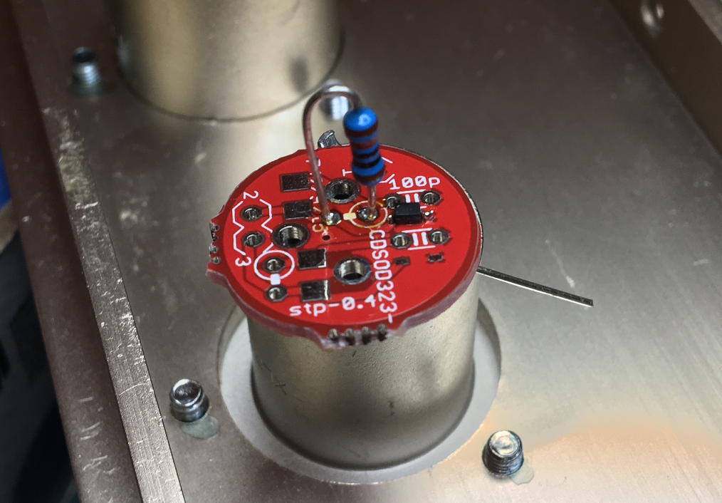
I just tested a Bourns CDSOD323-T12C-DSL low capacitance TVS diode. These are nice because they are pretty much optimal for directing surge currents and transients from signal lines to chassis pins instead of to supply lines. Most important, you can put them right next to the IO pins where they should be.
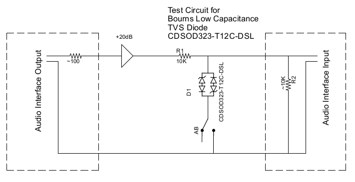
No one seems to be using these so I decided to tested one. Here's the test circuit:

These diodes come in 12V and 24V. The one I tested is 12V only because I don't have an amplifier that can produce that much output. The 12V one clips at ~15V. So I put 12.5V (25 Vpp) into the above circuit and recorded the result using a typical AB measurement. Here are the results:

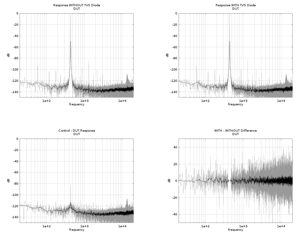
So the first two plots are A and B (with and without the TVS diode). The 3rd plot (lower left) is the spectrum of B - A and the final plot is the difference of the two spectrums.
The plots look noisy because of the high source impedance (10K) but the final plot shows pretty clearly that there is basically no difference between A and B other than expected differences due to noise.
No one seems to be using these so I decided to tested one. Here's the test circuit:

These diodes come in 12V and 24V. The one I tested is 12V only because I don't have an amplifier that can produce that much output. The 12V one clips at ~15V. So I put 12.5V (25 Vpp) into the above circuit and recorded the result using a typical AB measurement. Here are the results:

So the first two plots are A and B (with and without the TVS diode). The 3rd plot (lower left) is the spectrum of B - A and the final plot is the difference of the two spectrums.
The plots look noisy because of the high source impedance (10K) but the final plot shows pretty clearly that there is basically no difference between A and B other than expected differences due to noise.


![Electronics Soldering Iron Kit, [Upgraded] Soldering Iron 110V 90W LCD Digital Portable Soldering Kit 180-480℃(356-896℉), Welding Tool with ON/OFF Switch, Auto-sleep, Thermostatic Design](https://m.media-amazon.com/images/I/41gRDnlyfJS._SL500_.jpg)


